
Annular Sealing Assembly, in Particular for Wheel Hubs

a sealing assembly and hub technology, applied in the direction of mechanical equipment, rigid support of the bearing unit, transportation and packaging, etc., can solve the problems of easy loss of lubricant grease between the two lips, inability to meet the longer life requirements of the members, and inability to solve the problem of no longer satisfying the solution, etc., to achieve high sealing efficiency, low production cost, and high efficiency

Inactive Publication Date: 2009-04-30
AB SKF
View PDF9 Cites 11 Cited by
  • Summary
  • Abstract
  • Description
  • Claims
  • Application Information

AI Technical Summary

Benefits of technology

[0007]It is the object of the present invention to provide a sealing assembly for demanding applications, for example vehicle wheel hubs, which is capable of ensuring, also in the presence of high doses of external contaminants and preserving, at the same time, a low production cost, a high sealing efficiency and, above all, which is capable of maintaining such high efficiency essentially unvaried also with the progressive wear of the sealing lip.
[0013]In this way, the external contaminants can reach the first lip, which forms the main sealing lip, only very difficultly and after a relative long working time because they are withheld by the second lip; furthermore, the wear of the latter does not have direct consequences on the sealing capacity of the sealing assembly entirely remitted to the first lip, also because the first lip, thanks to its particular geometry, is capable of maintaining a constant and unaltered sealing action also facing relatively high wear of the same.

Problems solved by technology

Unfortunately, contaminants such as dust and mud, also if blocked by the sealing assembly, tend to blend with the grease lubricating the sealing lips and wear the latter off until they loose their entire sealing capacity.
In this way, however, the lubricant grease possibly placed between the two lips is easily lost outwards and the external contaminants, also if in minimum amount, may come into contact with the main sealing lip and cause consequent wear of the same.
However, such solution is no longer satisfying in view of the longer life required by the members.

Method used


Image

  • Annular Sealing Assembly, in Particular for Wheel Hubs
  • Annular Sealing Assembly, in Particular for Wheel Hubs
  • Annular Sealing Assembly, in Particular for Wheel Hubs

Examples


Embodiment Construction

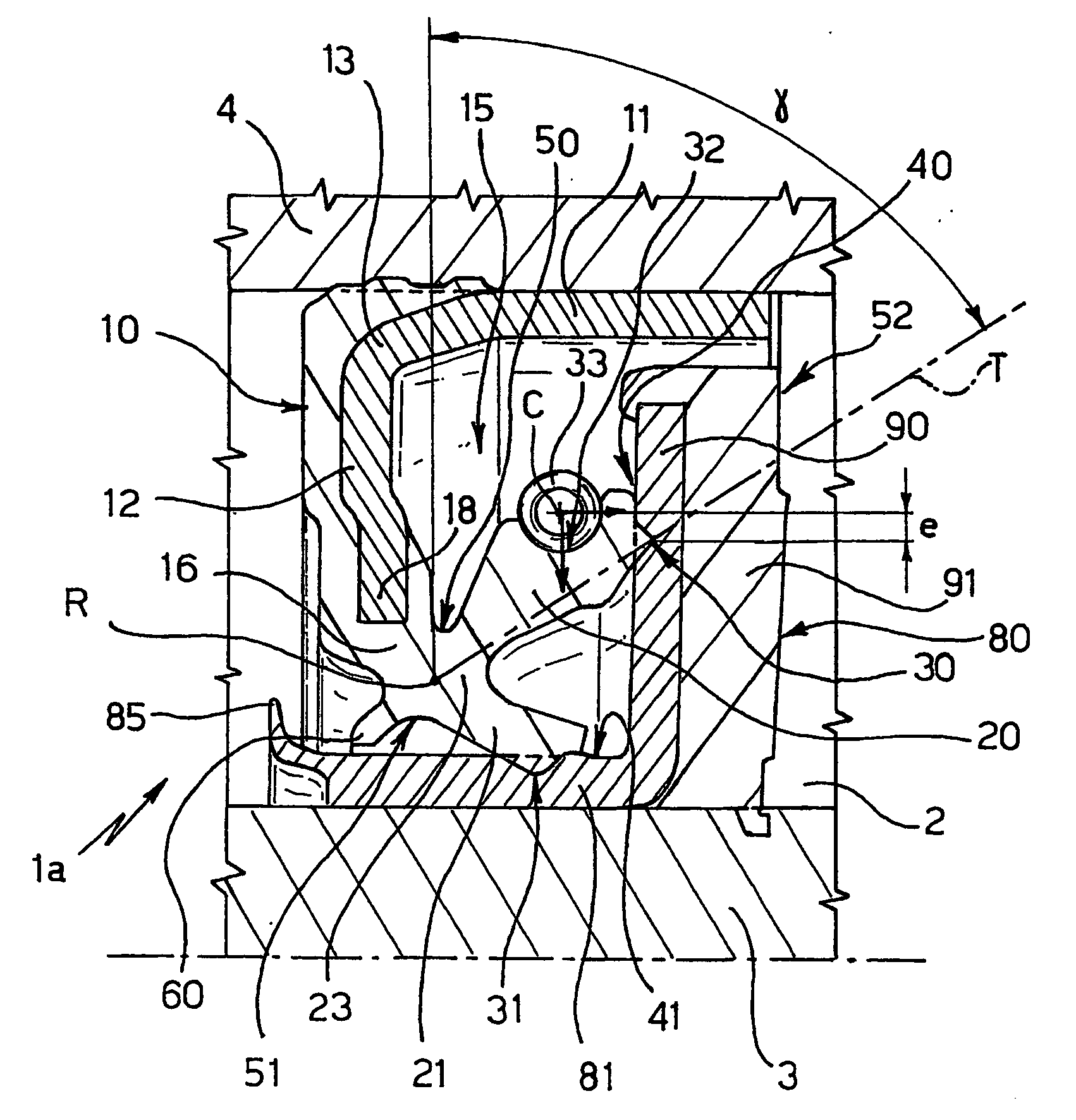
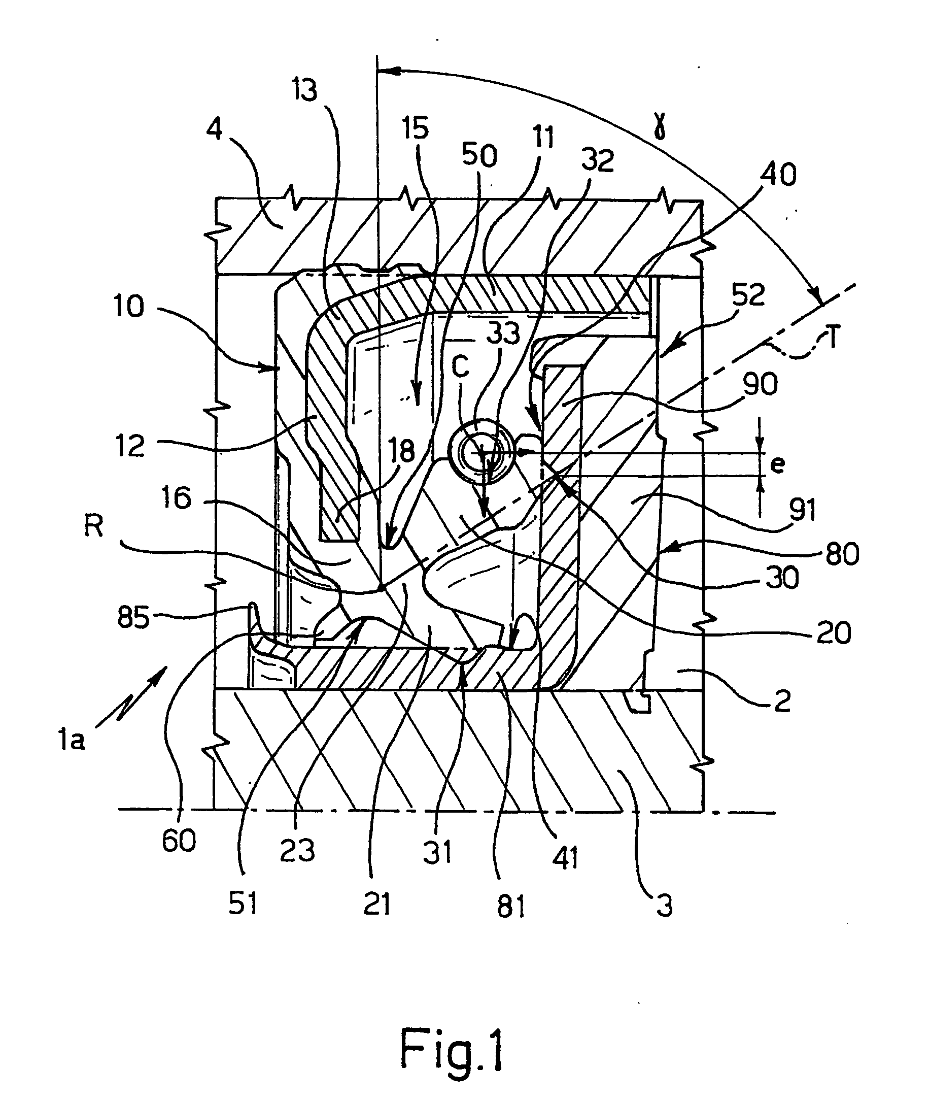
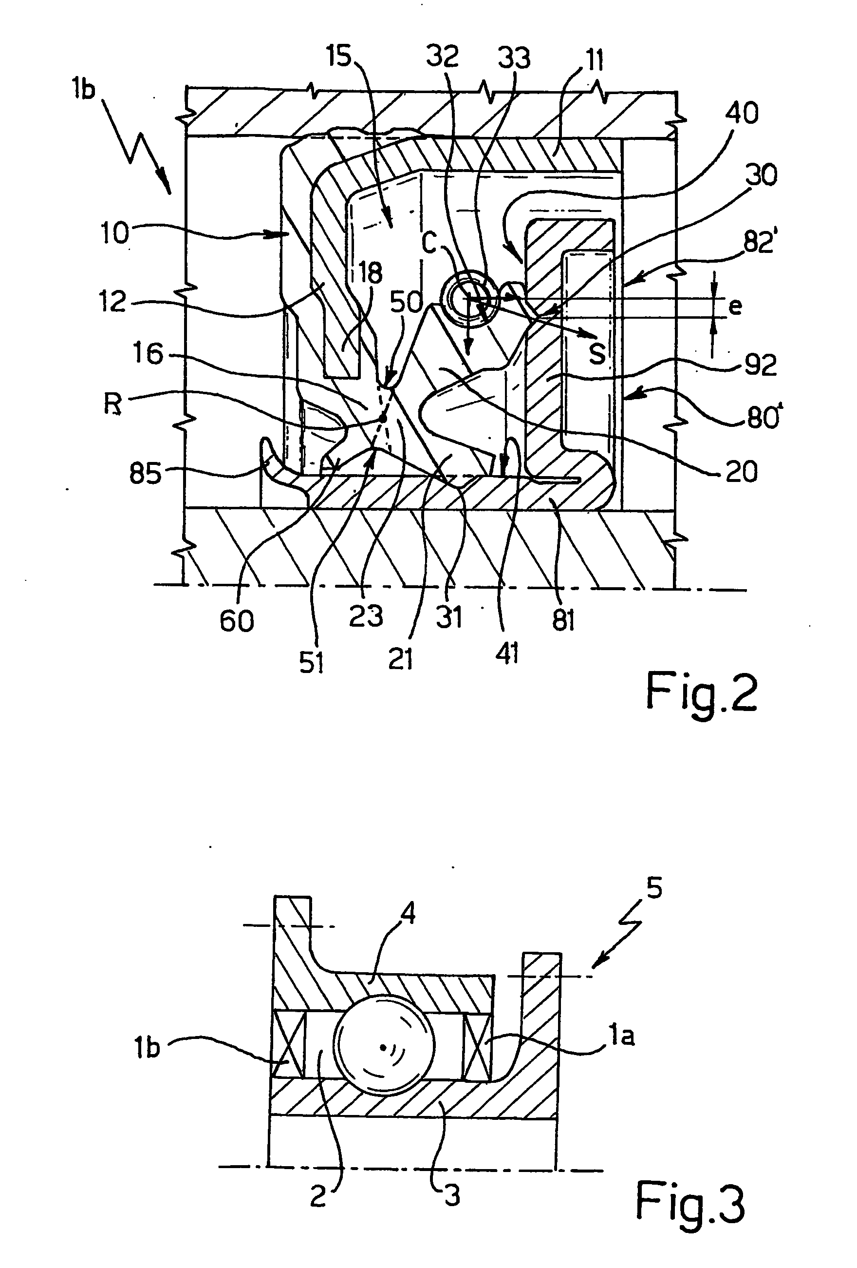
[0020]With reference to figures from 1 to 3, number 1 indicates a sealing assembly insertable in a compartment 2 defined between two relatively rotating members 3,4, in particular the inner 3 and outer 4 rings of a hub bearing unit 5 (FIG. 3) for vehicles, to isolate the compartment 2 from the outside environment.

[0021]The sealing assembly 1 comprises a first annular shield 10 presenting an axial sleeve portion 11 for angularly and integrally mounting with one of said members, in the case in point with the outer ring 4, and a flange portion 12 which radially extends from a first end 13 of the sleeve portion 11.

[0022]The sealing assembly 1 further comprises a sealing member 15 integrally carried by the shield 10 and made of elastomeric material (for example a natural or synthetic rubber) presenting an annular root portion 16 which radially and overhangingly protrudes from a peripheral edge 18 of the flange portion 10, a first axial sealing annular lip 20 and a second radial sealing a...


PUM


Abstract

A sealing assembly (1a, 1b) including: a first annular shield (10) presenting a sleeve portion (11) and a flange portion (12) which extends radially from a first end (13) of the sleeve portion; and a sealing member (15) made of elastomeric material presenting an annular root portion (16) which extends radially and overhangingly from a peripheral edge (18) of the flange portion and a first axial annular sealing lip (20) in which the sealing member presents a second radial annular sealing lip (21), the lips (20, 21) axially and overhangingly extending from the opposite side of the first end of the sleeve portion, on a same side as a thinned end (23) of the root portion and being reciprocally spread to form a radial V-shaped section having vertex facing the root portion and axis parallel to the sleeve portion; the first lip presenting a radial seat (32) facing the opposite side of the second lip and accommodating a toroidal spring (33) applying an offset radial stress to an elastic hinge defined by the thinned end of the root portion, —the sealing lips may be coupled to a second and a third annular shields selectively arrangeable coaxial to the first shield (50,50′) and having similar dimensions.

Description

TECHNICAL FIELD[0001]The present invention relates to an annular seal assembly of the type intended to protect the rolling bearings of a wheel hub from external contaminants, such as water, dust, mud, with which the wheel hub is constantly in contact during the operative life.[0002]In particular, the sealing assembly of the invention is suitable for advantageously equipping a hub bearing unit of a known type, whose hub and spindle functions are performed by the rings of a rolling bearing, which are appropriately flanged so as to receive on one side a wheel of a vehicle and on the other be fastened to the upright of a vehicle suspension.BACKGROUND ART[0003]It is known that, in automotive applications, the rolling bearings, in particular those present in wheel hubs, and more in particular those forming the hub bearing unit of the aforesaid type, are continuously exposed, in use, to the contact with high quantities of contaminants: therefore, in such applications, the sealing assemblie...

Claims


Application Information

Patent Timeline
IPC IPC(8): F16J15/32
CPCF16C33/7879F16C2326/02F16J15/3256F16C41/007F16C19/06F16C33/76F16C33/78F16C35/00F16C19/00
Inventor FORTI, CLAUDIOSERAFINI, ANDREABRUNETTI, MARCO
Owner AB SKF
Learn More