
Interbody fusion device, integral retention device, and associated methods

a technology of interbody fusion and fusion device, which is applied in the field of spinal fusion, can solve the problems of degeneration of the spine, pain and/or nerve damage, and destabilization of the spine, and achieve the effect of preventing the migration of the interbody fusion devi

Active Publication Date: 2009-04-23
SPINESMITH PARTNERS
View PDF39 Cites 234 Cited by
  • Summary
  • Abstract
  • Description
  • Claims
  • Application Information

AI Technical Summary

Benefits of technology

[0010]Another embodiment of the invention provides a method of fusing adjacent vertebrae including inserting an interbody fusion device between two adjacent vertebrae, preparing the end plates of the vertebrae for fusion by accessing the end plates through one or more openings formed in the interbody fusion device, and securing a retention device to interbody fusion device to prevent migration of the interbody fusion device.

Problems solved by technology

Due to trauma, disease, and / or aging, the spine may be subject to degeneration.
This degeneration may destabilize the spine and cause pain and / or nerve damage.
One problem with prior art spinal fusion techniques relates to device migration.
In examples where bone screws are used, the insertion and tightening of the bone screws tends to cause device migration.
Another problem with typical prior art fusion techniques is that fusion devices, or associated plates or fasteners, protrude from the spine, causing discomfort, damage, or danger to surrounding vascular or neurological tissues.
Another problem with prior art spinal fusion techniques relates to preparing the end plates of the vertebrae for fusion.
This procedure can be difficult and not exact.
In addition, there is a danger of damaging nearby tissue while scraping the end plates.

Method used


Image

  • Interbody fusion device, integral retention device, and associated methods
  • Interbody fusion device, integral retention device, and associated methods
  • Interbody fusion device, integral retention device, and associated methods

Examples


Embodiment Construction

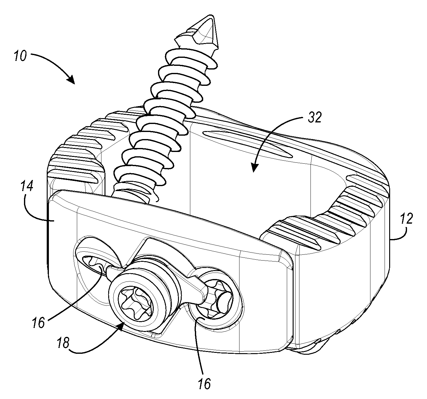
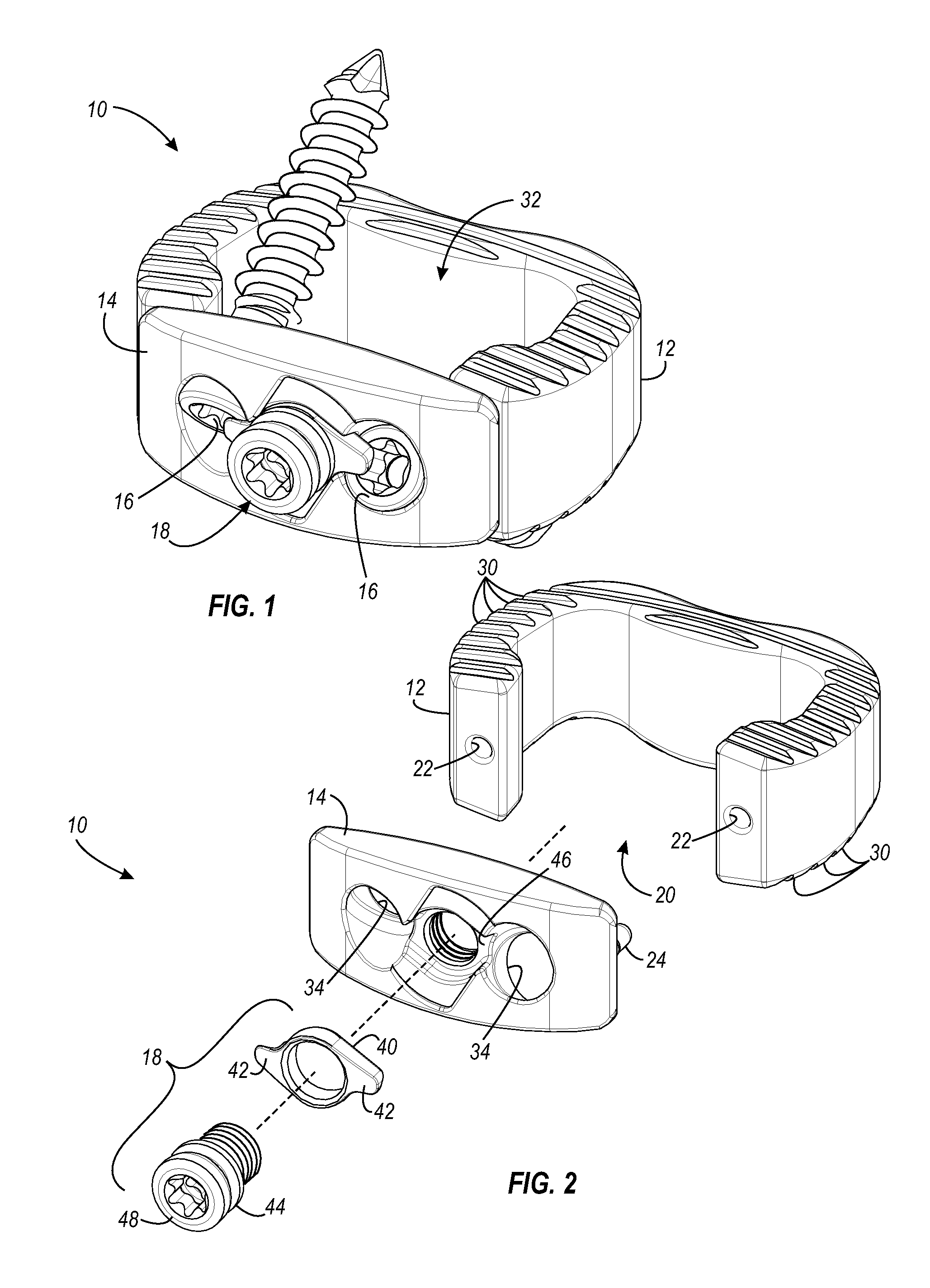
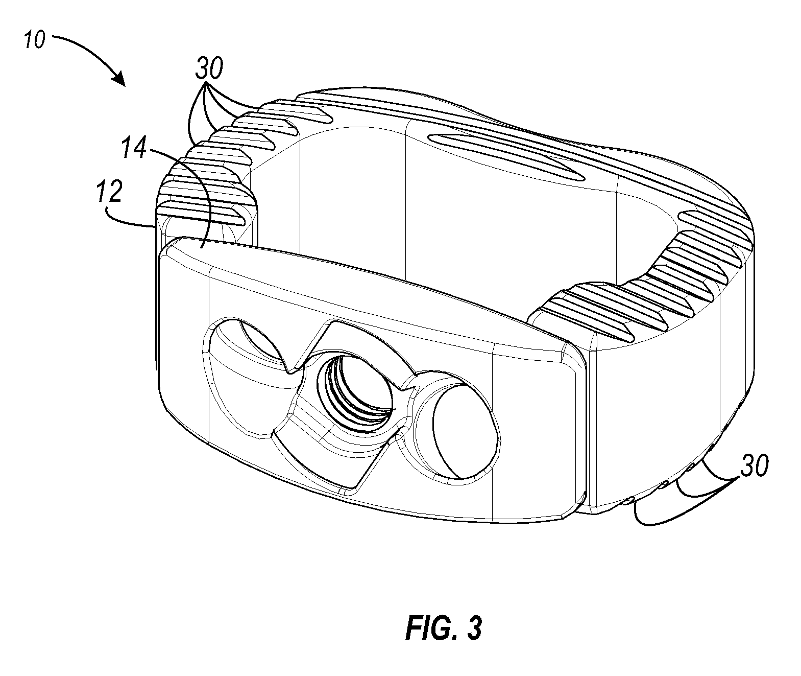
[0026]The present invention relates to spinal fusion implants and related spinal fusion procedures for use in cervical and lumbar applications. One type of spinal fusion is interbody fusion. Typically, an interbody fusion procedure places a bone graft between the vertebra in the area normally occupied by an intervertebral disc. In preparation for a spinal fusion procedure, the intervertebral disc is removed. The end plates are then scraped to prepare the end plates for fusion. Scraping the end plates will disrupt the boney tissue, causing the tissue to bleed, heal, and fuse through the interbody fusion implant. An interbody device may be placed between the vertebra to maintain spine alignment and disc height. Fusion then occurs between the endplates of the vertebrae. In some examples, fusion is augmented by a process called fixation, meaning the placement of screws, rods or plates to stabilize the vertebra to facilitate bone fusion. The present invention provides an interbody fusion...


PUM


Abstract

A method and apparatus is provided for use in spinal fusion procedures. A one or two piece interbody fusion device has a fusion bearing component designed to bear the axial loading from the end plates of adjacent vertebrae. An optional retention piece prevents migration of the load bearing device. One or more fasteners secure the retention device to the vertebrae above and below the load bearing device. The fasteners cause the end plates of the vertebrae to compress the end plates to the load bearing device to facilitate proper fusion. An anti-backout mechanism prevents the fasteners backing out.

Description

CROSS REFERENCE TO RELATED APPLICATIONS[0001]This application claims priority under 35 U.S.C. §119 / 120 to co-pending, commonly owned United States provisional patent application Ser. No. 60 / 981,414, attorney docket number SPU.P0109P, filed on Oct. 19, 2007, entitled “INTERBODY FUSION DEVICE AND ASSOCIATED METHODS”, which is incorporated by reference herein.FIELD OF THE INVENTION[0002]This invention relates to the field of spinal fusion. In particular, this invention is drawn to spinal fusion devices and associated methods.BACKGROUND OF THE INVENTION[0003]The spine can be considered to be a series of movable segments made up of vertebrae and discs. Due to trauma, disease, and / or aging, the spine may be subject to degeneration. This degeneration may destabilize the spine and cause pain and / or nerve damage. Medical procedures are often required to either ease back pain, repair damage, or to prevent future damage.[0004]One procedure that is often used to treat back pain or spinal damage...

Claims


Application Information

Patent Timeline
Patent Type & Authority Applications(United States)
IPC IPC(8): A61F2/44A61B17/56
CPCA61B17/8033A61F2230/0065A61F2/30744A61F2/4455A61F2/4465A61F2002/2835A61F2002/30131A61F2002/302A61F2002/30352A61F2002/30383A61F2002/30604A61F2002/30904A61F2220/0025A61F2220/0033A61F2230/0013A61B17/86A61B17/8042
Inventor JONES, ROBERT J.RAHM, MARKDUNWORTH, KEVIN
Owner SPINESMITH PARTNERS
Learn More