
Apparatus for selectively rotating and/or advancing an elongate device

a technology of elongate devices and actuators, which is applied in the direction of friction gearings, gearings, surgery, etc., can solve the problems of exposing the physician or healthcare professional to radiation, not allowing precise control, and easy fatigue of the person manipulating the devi

Active Publication Date: 2009-04-23
STEREOTAXIS
View PDF6 Cites 135 Cited by
  • Summary
  • Abstract
  • Description
  • Claims
  • Application Information

AI Technical Summary

Problems solved by technology

While effective, this method does not permit precise control, and the person manipulating the device can easily fatigue.
Furthermore, this method often exposes the physician or healthcare professional to radiation from the imaging systems used to monitor the procedure.
However a simple, reliable device that is capable of selectively advancing, retracting and rotating a device has not been previously available.

Method used


Image

  • Apparatus for selectively rotating and/or advancing an elongate device
  • Apparatus for selectively rotating and/or advancing an elongate device
  • Apparatus for selectively rotating and/or advancing an elongate device

Examples


fourth embodiment

[0055]The fourth embodiment accordingly includes a drive shaft having a plurality of drive gears, the drive shaft being moveable to a first position in which a first drive gear engages the first ring gear only to cause the rotation of the carrier having a roller that engages the device, and also the bevel gear on the carrier that drives the roller engaging the device, to thereby advance the device while rotating the device about its axis, the drive shaft being movable to a second position in which a second drive gear engages the second ring gear only such that the first ring gear and carrier remain stationary, to cause the rotation of the bevel gear on the carrier that drives the roller engaging the device, to thereby advance the device without rotating the device, the drive shaft being movable to a third position in which a third and fourth drive gear respectively engage the first ring gear and the second ring gear, to cause a rotation at the same speed of both the bevel gear and t...

third embodiment

[0056]By coordinating the linear position of drive shaft 310 and engagement of drive gears 312, 314, 316 and 318, as well as the rotational direction and speed of the drive shaft 310, the simultaneous rotation of ring gear 214 or 238 (or both ring gears 214 and 238) can allow a device D adjacent the master drive roller to be rotated with or without advancement, or to advance the device with or without rotation, such that the device D can be advanced at a selected rate and / or in a desired rotational direction, by rotation of a single drive shaft (unlike the rotation of two worm gears as in the third embodiment above). Additionally, the system may be configured to constrain the ring gears 214 and 238 from rotation when they are not engaged with a drive gear on drive shaft 310, by use of a brake or friction device 320 for engaging the ring gears 214 and 238, for example, as shown in FIG. 15. Alternatively, the motor driving the drive shaft 310 may employ a dynamic breaking phenomenon t...


PUM


Abstract

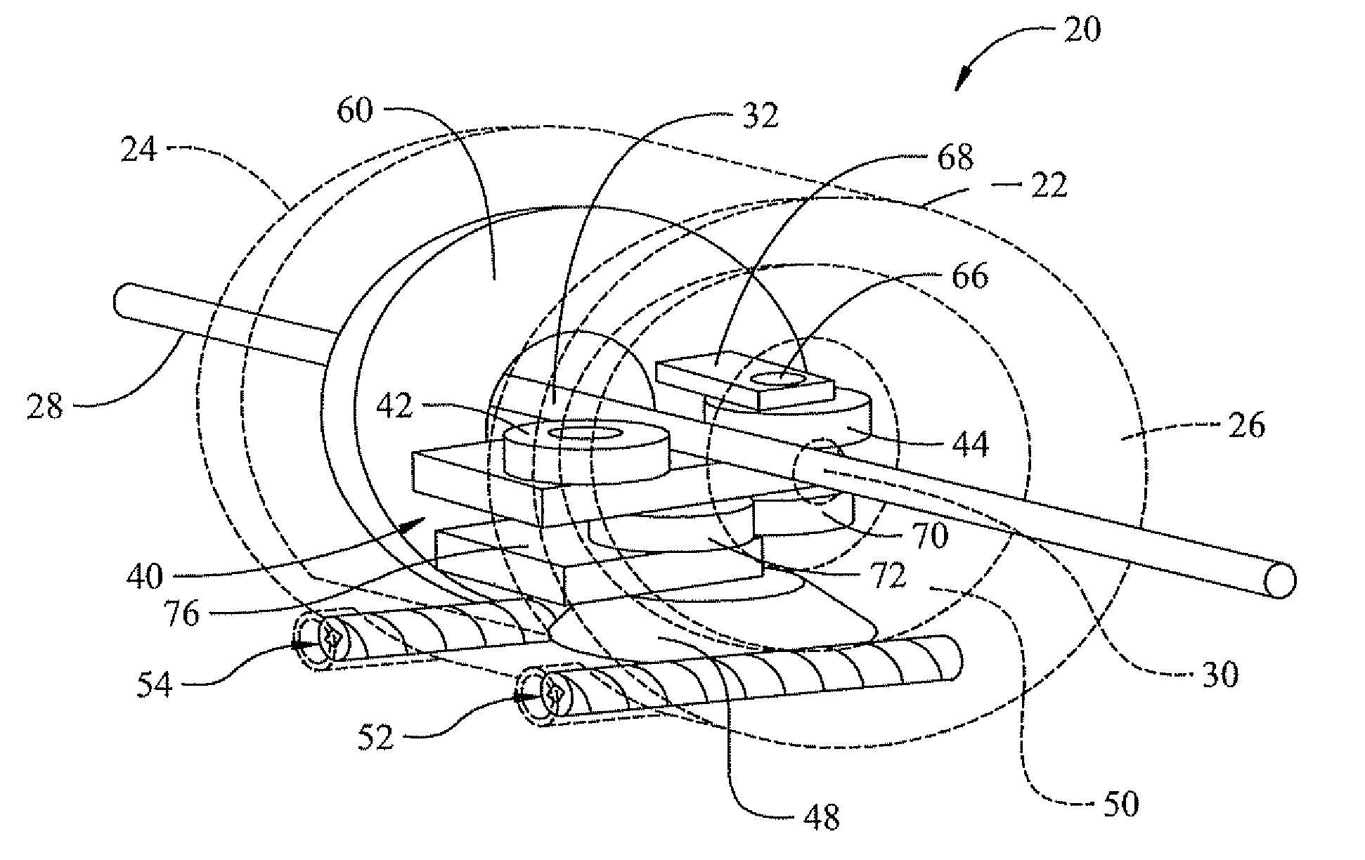
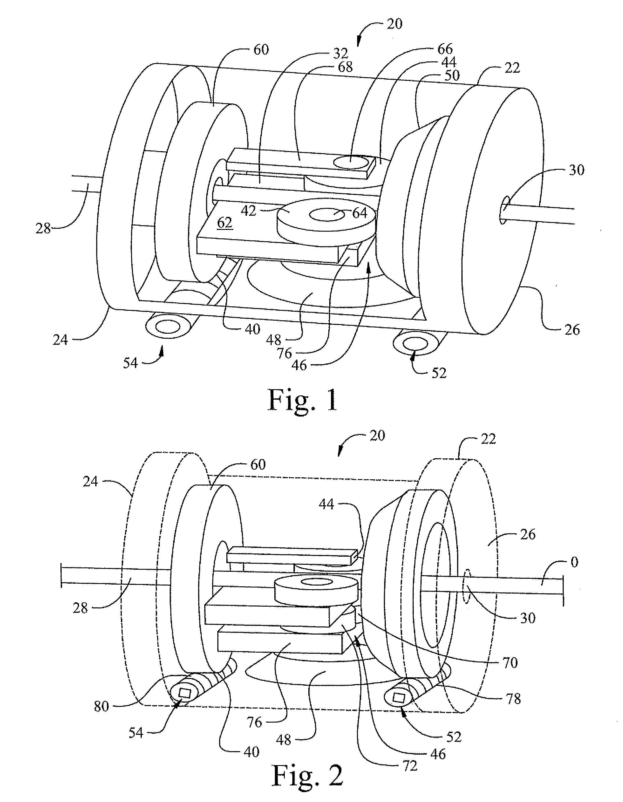
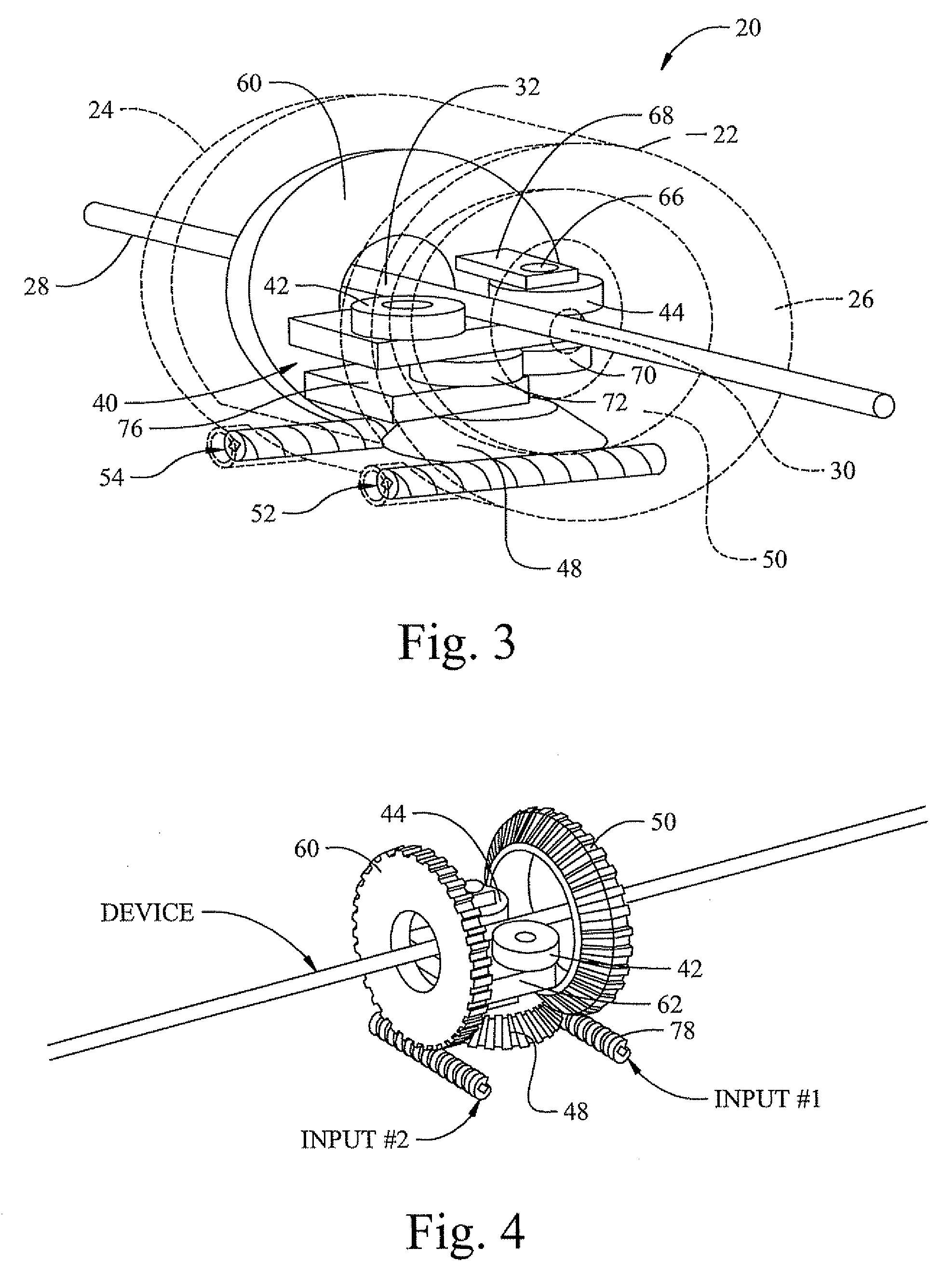
An apparatus for selectively advancing and / or rotating an elongate device, includes a carrier mounted for rotation about a primary axis and a pair of opposed rollers on the carrier adapted to receive and engage an elongate device between them, and drive the device in a direction along the primary axis. A drive mechanism for driving at least one of the pair of opposed rollers, the drive mechanism comprising a first gear pivotally mounted about a first axis perpendicular to the primary axis, a second gear engaging the first gear, rotatably mounted about an axis parallel to the primary axis. A first input for selectively rotating the second gear in first or second directions to advance or retract an elongate device engaged by the pair of opposed rollers. A second input for selectively rotating the carrier in first and second directions to rotate an elongate device engaged by the pair of opposed rollers. The operation of the second input alone simultaneously rotating and advancing or retracting the elongate device, and the coordinated operation of the first and second inputs allowing rotation of the elongate device without advancement or retraction of the elongate device.

Description

CROSS-REFERENCE TO RELATED APPLICATIONS[0001]This application is a continuation-in-part of U.S. patent application Ser. No. 12 / 196,058 filed on Aug. 21, 2008, which claims the benefit of U.S. Provisional Application No. 60 / 957,008, filed on Aug. 21, 2007. The entire disclosures of each of the above applications are incorporated herein by reference.FIELD[0002]The present disclosure relates to an apparatus for selectively rotating and / or advancing or retracting an elongate device, such as a medical catheter or guidewire.BACKGROUND[0003]This section provides background information related to the present disclosure which is not necessarily prior art. In many medical procedures it is common to advance an elongate device such as a catheter or guidewire into the body. In at least some of these procedures, it can also be desirable to rotate the device as well. Generally this is accomplished by the physician or other health care professional grasping the proximal portion of the device and pu...

Claims


Application Information

Patent Timeline
Patent Type & Authority Applications(United States)
IPC IPC(8): A61M29/00
CPCA61M25/0113A61M25/09041A61M25/0136A61M25/0133
Inventor KIDD, BRIANHITCHENS, RICHARD
Owner STEREOTAXIS
Learn More