
Hermetic receiver package

Inactive Publication Date: 2009-04-23
SOLFOCUS
View PDF18 Cites 66 Cited by
  • Summary
  • Abstract
  • Description
  • Claims
  • Application Information

AI Technical Summary

Benefits of technology

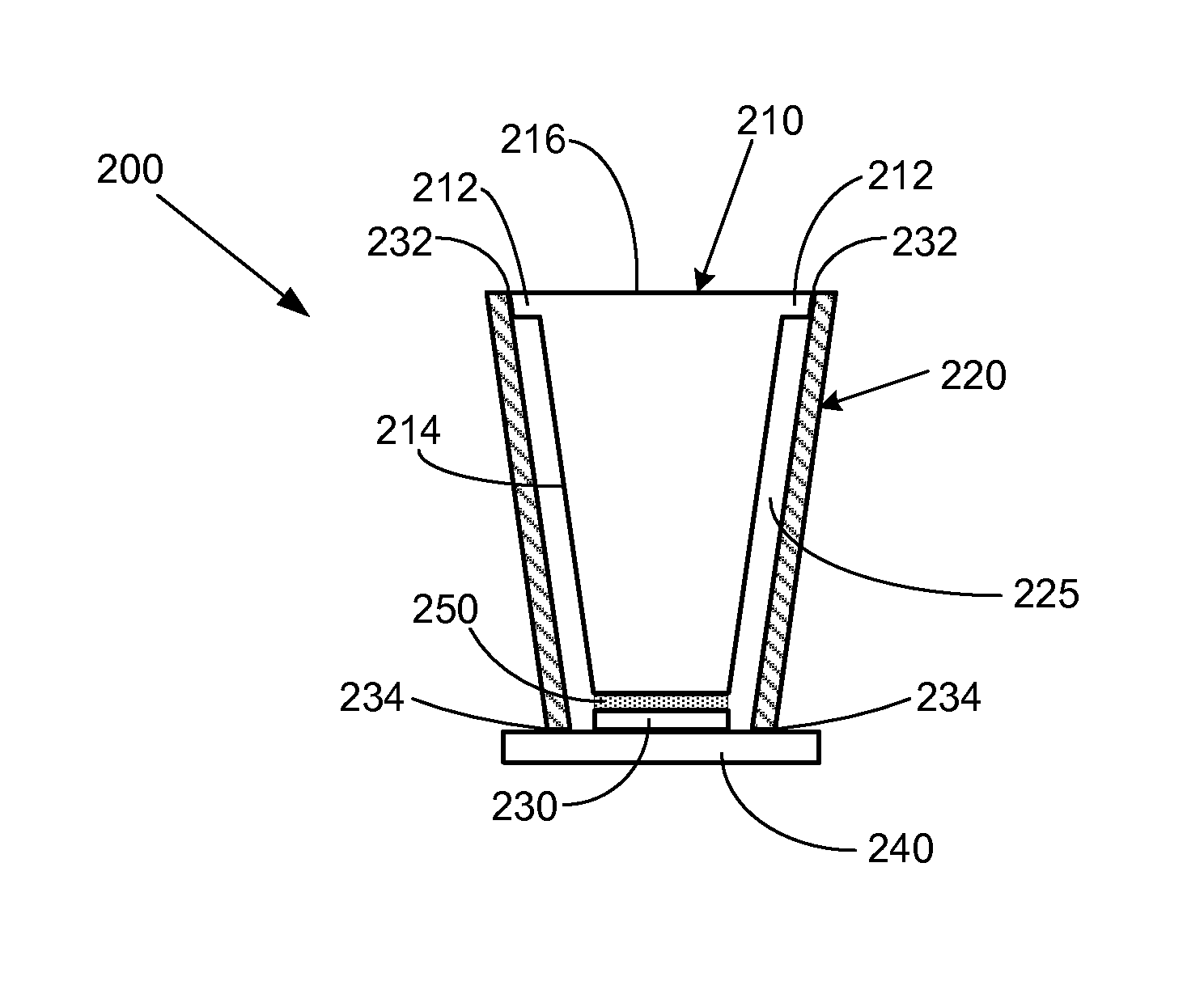
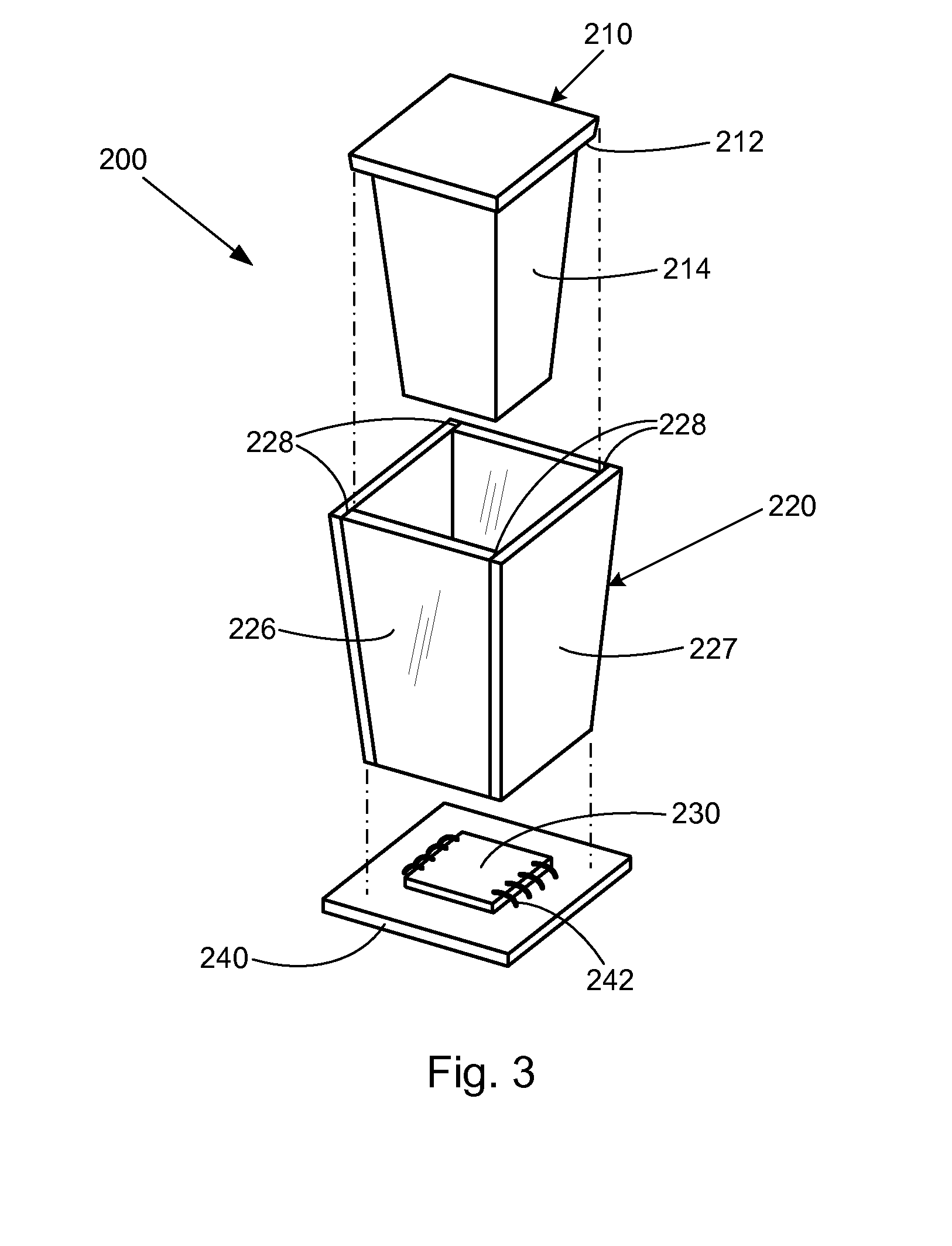
[0006]The present invention is a hermetic receiver package for improving reliability of optical components within a solar concentrator system. The hermetic receiver package includes a non-imaging concentrator and a solar cell sealed within a shell structure to provide protection from environmental degradation. The non-imaging concentrator and solar cell are guarded from degradation caused by the outside environment as well as by sources within the solar concentrator system. In one embodiment, the shell may be manufactured in a cost-effective manner from standard sheet glass. In other embodiments, manufacturing features facilitate spacing and alignment between the non-imaging concentrator and shell during assembly of the hermetic receiver package.

Problems solved by technology

Dirt, debris, airborne chemicals, moisture, and the like can hinder the optical performance of the various components as well as cause degradation of materials over time.

Method used


Image

  • Hermetic receiver package
  • Hermetic receiver package
  • Hermetic receiver package

Examples


Embodiment Construction

[0015]Reference now will be made in detail to embodiments of the disclosed invention, one or more examples of which are illustrated in the accompanying drawings.

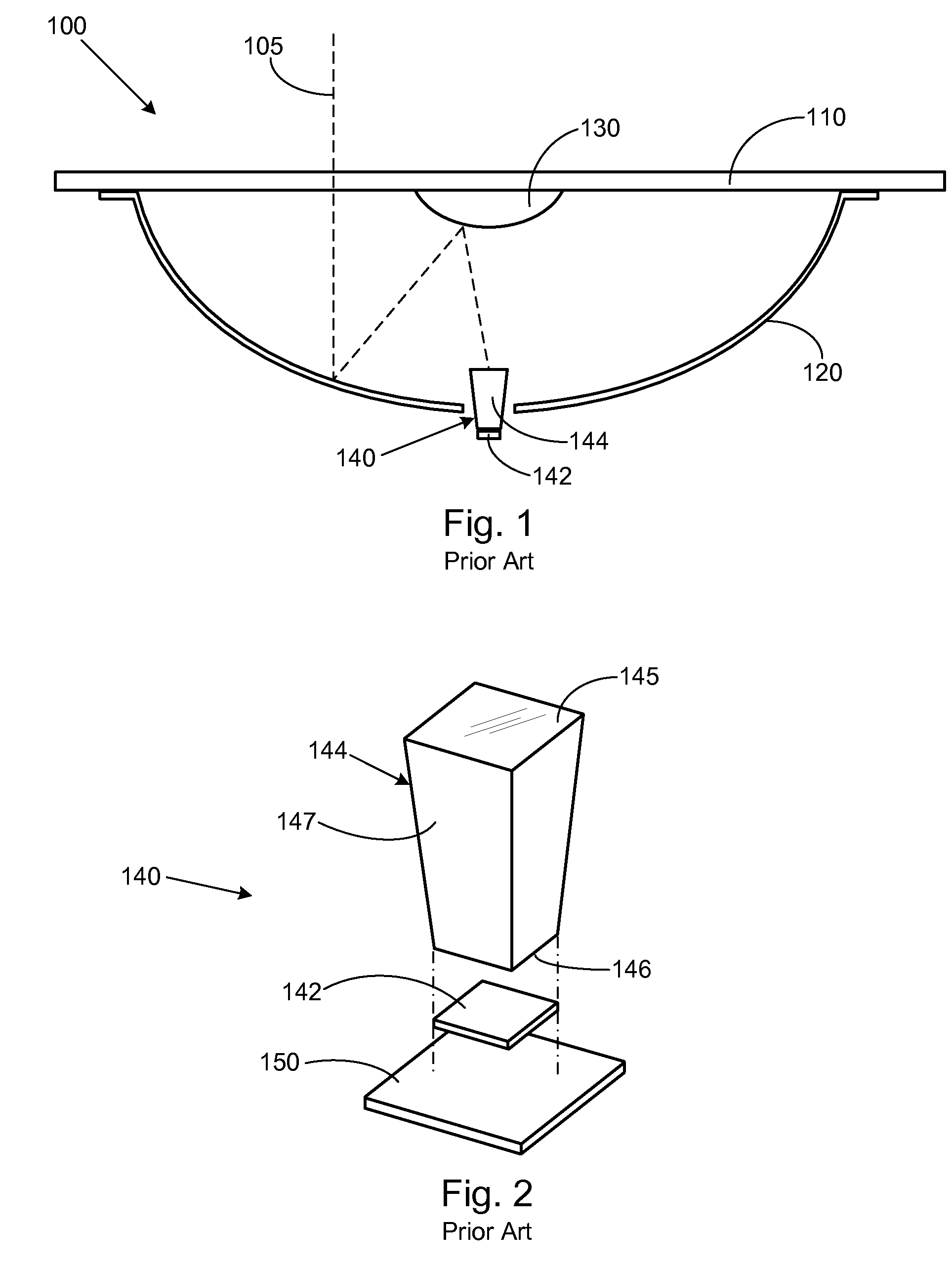
[0016]FIG. 1 depicts a cross-sectional view of an exemplary solar concentrator unit 100 as disclosed in U.S. Patent Publication No. 2006 / 0266408, entitled “Concentrator Solar Photovoltaic Array with Compact Tailored Imaging Power Units.” Solar radiation 105, represented by dashed lines, enters solar concentrator unit 100 through a front panel 110, reflects off a primary mirror 120 and secondary mirror 130, and then enters an optical receiver 140. Optical receiver 140 includes a photovoltaic solar cell 142, also referred to as a “die,” where solar radiation 105 is converted to electricity, and may also include a non-imaging concentrator 144. Non-imaging concentrator 144 serves as a conduit to deliver solar radiation 105 to solar cell 142. Non-imaging concentrator 144 provides the potential to increase the acceptance angle of ...


PUM

PropertyMeasurementUnit
Temperatureaaaaaaaaaa
Shapeaaaaaaaaaa
Distanceaaaaaaaaaa

Abstract

The present invention is a hermetic receiver package for improving reliability of optical components within a solar concentrator system. The hermetic receiver package includes a non-imaging concentrator and a solar cell sealed within a shell structure to provide protection from environmental degradation. The non-imaging concentrator and solar cell are guarded from degradation caused by the outside environment as well as by sources within the solar concentrator system. Features are incorporated into the non-imaging concentrator and shell which allow the hermetic receiver package to be manufactured in a cost-effective manner.

Description

RELATED APPLICATIONS[0001]This application claims priority to U.S. Provisional Patent Application Ser. No. 60 / 980,773 filed on Oct. 17, 2007 entitled “Hermetic Receiver Package,” which is hereby incorporated by reference as if set forth in full in this application for all purposes.BACKGROUND OF THE INVENTION[0002]Solar concentrators are solar energy generators which increase the efficiency of converting solar energy into DC electricity. Solar concentrators known in the art utilize, for example, parabolic mirrors and Fresnel lenses for focusing incoming solar energy, and heliostats for tracking the sun's movements in order to maximize light exposure. Another type of solar concentrator, disclosed in U.S. Patent Publication No. 2006 / 0266408, entitled “Concentrator Solar Photovoltaic Array with Compact Tailored Imaging Power Units,” utilizes a front panel for allowing solar energy to enter the assembly, with a primary mirror and a secondary mirror to reflect and focus solar energy throu...

Claims


Application Information

Patent Timeline
IPC IPC(8): H01L31/0232H01L31/18
CPCH01L31/18Y10T29/49002H01L31/0547Y02E10/52
Inventor MILBOURNE, MICHAELACKLER, HAROLD
Owner SOLFOCUS
Learn More