Self repairing roof membrane
- Summary
- Abstract
- Description
- Claims
- Application Information
AI Technical Summary
Benefits of technology
Problems solved by technology
Method used
Image
Examples
example 1
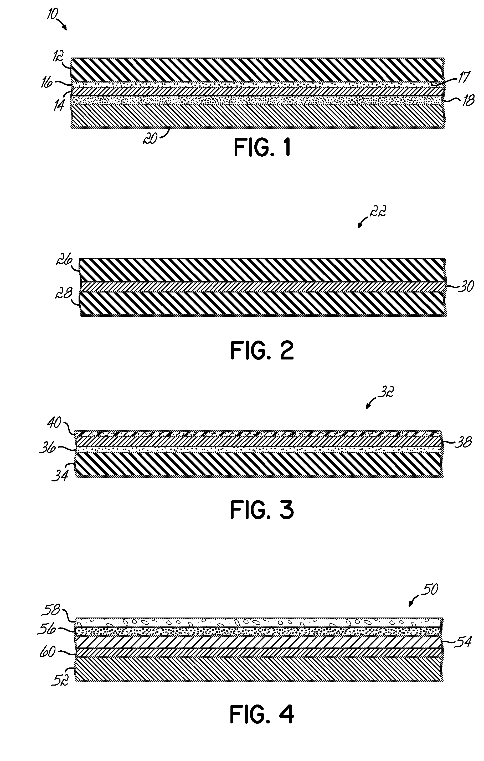
[0023]Samples of various grades of water swellable polymer (WSP) impregnated on a nonwoven fabric were obtained from Neptco, Inc. Laboratory samples (about 0.060-0.070 inches) were prepared by placing the WSP impregnated nonwoven fabric between two pieces of uncured EPDM rubber, as shown in FIG. 2. Press-cure samples were obtained after heating at 320° F. for 35 minutes (2,000-5,000 psi). To simulate a cut in the membrane, a 1-inch gash was cut through the sample. A 3-inch×2-inch cylinder was positioned over the gash and adhered to the sample with plumbers putty. The system was tested by dripping 25 ml of water from a burette over a 1-minute period. After the WSP had swelled, an additional 150 ml of water was added to the system in the same manner over a 3-minute period. The amount of water that had passed through the system was recorded every hour. Using this system, leakage was slowed by 26.0-93.0%.
example 2
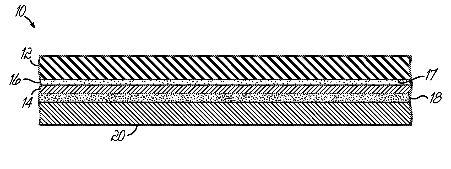
[0024]Samples were prepared by attaching the WSP impregnated nonwoven fabric to the bottom of a standard 0.045-inch EPDM membrane using a polyethylene hot melt adhesive (see FIG. 1).
[0025]Samples were damaged by cutting a 1-inch gash through the entire sample. The test assembly was prepared as previously described. Samples were tested by dripping 125 ml of water over a 10-minute period. Results were recorded every 15 minutes for one hour, and then after an additional hour. The results of the experiment are shown in Table 1.
TABLE 1Self Repairing Membrane, WSP nonwoven on bottom of membraneTime (min)Control123Water through sample (ml)15111 (88.8%)1 (0.8%) 2 (1.6%) 5 (4%)30 12 (85%)010 (8%) 9 (7.5%)45 0017 (15%)30 (27.5%)60 00 0 0120 00 0 0Total123 (98.4%)1 (0.8%)29 (23.2%)39 (31.2%)
[0026]The control leaked about 89% of the water introduced in the system within the first 15 minutes, and 85% of the remaining water over the following 15 minutes. In one case, the experimental sample leak...
example 3
[0028]Samples were prepared by attaching the WSP nonwoven to the bottom of a membrane as previously described (see FIG. 1). The membrane and nonwoven composite were adhered to two pieces of polyisocyanurate insulation with Carlisle Sure-Seal 90-8-30A Bonding Adhesive. Damage was introduced to the system with two ½-inch, 45° cuts into the membrane simulating a tear. In order to investigate a worst case scenario, the damage was inflicted over the void space between the two pieces of insulation. The test assembly was prepared as previously described.
[0029]Water was introduced to the system via a burette at the rate of 125 ml (volume of about 1.75 in) over a 15-minute period to simulate a heavy rainstorm. Results were recorded every 15 minutes for one hour, and then after an additional hour. The results of the experiment are shown in Table 2.
TABLE 2Prototype testing - Simulated Tear ResultsTime (min)Control123Water through sample (ml)15125151530—0.501645—0.501560—0.50120 —10Total125 (10...
PUM
| Property | Measurement | Unit |
|---|---|---|
| Volume | aaaaa | aaaaa |
| Volume | aaaaa | aaaaa |
| Volume | aaaaa | aaaaa |
Abstract
Description
Claims
Application Information
 - R&D
- Intellectual Property
- Life Sciences
- Materials
- Tech Scout
- Unparalleled Data Quality
- Higher Quality Content
- 60% Fewer Hallucinations
Browse by: Latest US Patents, China's latest patents, Technical Efficacy Thesaurus, Application Domain, Technology Topic, Popular Technical Reports.
© 2025 PatSnap. All rights reserved.Legal|Privacy policy|Modern Slavery Act Transparency Statement|Sitemap|About US| Contact US: help@patsnap.com


