Method and Apparatus for Control and Safe Braking in Personal Rapid Transit Systems with Linear Induction Motors

Inactive Publication Date: 2009-04-16
POHANG IRON & STEEL CO LTD
View PDF6 Cites 13 Cited by
  • Summary
  • Abstract
  • Description
  • Claims
  • Application Information

AI Technical Summary

Benefits of technology

[0025]Enhanced level of safety by a vehicle-based system for emergency braking not depending on power and commands from outside.
[0026]Reduced risk for unnecessary braking due to a confirmed free distance being known at each time.
[0027]Not need for doubling power supply, motors and communication channels.
[0028]Can be combined with doubling of components for increased reliability.
[0029]The present invention relates to different aspects including the control system described above and in the following, a vehicle, a rapid transit system, and method, each yielding one or more of the benefits and advantages described in connection with the above-mentioned control system, and each having one or more embodiments corresponding to the embodiments described in connection with the above-mentioned system.
[0030]More specifically, according to another aspect, a vehicle is provided for a personal rapid transit system, the personal rapid transit system including a vehicle propulsion system including one or more motors, each motor being adapted to generate a thrust for propelling the vehicle, the rapid transit system further comprising a speed regulation subsystem adapted to control the thrust generated by at least one of said motors so as to control the speed of the vehicle based on one or more sensor signals received from position and / or speed sensors in the vehicle or in the guideway. The vehicle comprises: a vehicle control system included in said vehicle and adapted to activate, independently from the speed control by the speed regulation subsystem, an emergency brake monted on said vehicle.

Problems solved by technology

Therefore, the construction cost of the PRT system is much lower than that of alternative solutions.

Method used


Image

  • Method and Apparatus for Control and Safe Braking in Personal Rapid Transit Systems with Linear Induction Motors
  • Method and Apparatus for Control and Safe Braking in Personal Rapid Transit Systems with Linear Induction Motors
  • Method and Apparatus for Control and Safe Braking in Personal Rapid Transit Systems with Linear Induction Motors

Examples


Embodiment Construction

[0070]In-track Type Linear Induction Motor:

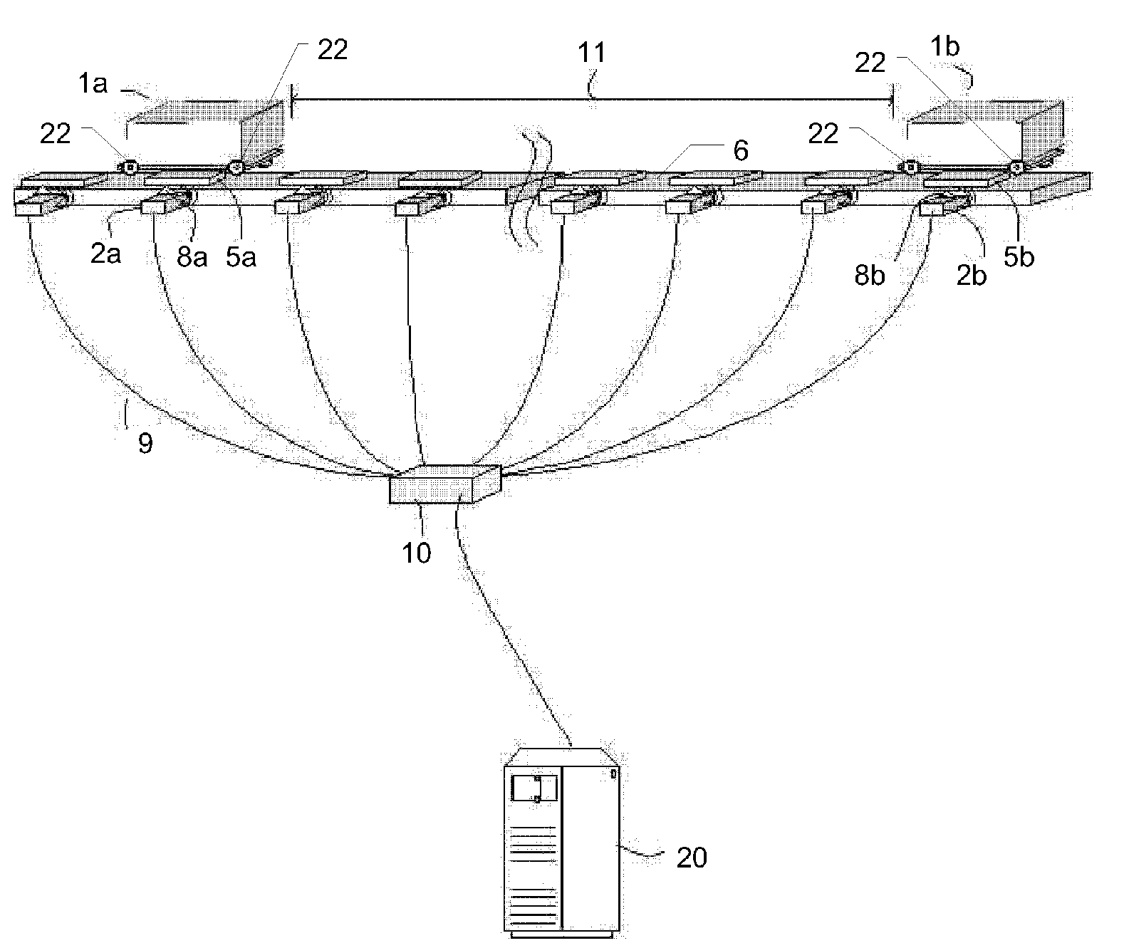
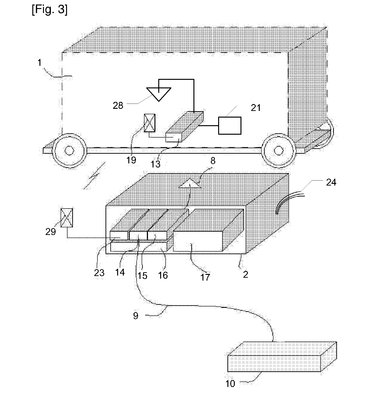
[0071]FIGS. 1 and 2 schematically show an example of a part of a personal rapid transit system with in-track type linear induction motor. The personal rapid transit system comprises a track, a section of which is shown in FIGS. 1 and 2 designated by reference numeral 6. The track typically forms a network, typically including a plurality of merges, diverges and stations. The personal rapid transit system further includes a number of vehicles, generally designated by reference numeral 1. FIG. 1 shows a track section 6 with two vehicles 1a and 1b, while FIG. 2 shows an enlarged view of a single vehicle 1. Even though only two vehicles are shown in FIG. 1, it is understood that a personal rapid transit system may include any number of vehicles. Generally, each vehicle typically includes a passenger cabin supported by a chassis or framework carrying wheels 22. An example of a PRT vehicle is disclosed in international patent application WO 04 / 09...


PUM


Abstract

A speed control system for controlling vehicle speed of one or more vehicles in a personal rapid transit system when the one or more vehicles travel along a track, the personal rapid transit system including a vehicle propulsion system including one or more motors, each motor being adapted to generate a thrust for propelling one of the one or more vehicles. The speed control system includes: a speed regulation subsystem adapted to control the thrust generated by at least one of said motors based on one or more sensor signals received from vehicle position and / or speed sensors, so as to control the speed of the one or more vehicles; and a vehicle control system included in each of said one or more vehicles and adapted to activate, independently from the speed regulation subsystem, an emergency brake mounted on said vehicle.

Description

TECHNICAL FIELD[0001]The present innovation relates to speed control and, in particular, safe braking in so called Personal Rapid Transit systems (referred to as “PRT”) propelled by linear induction motors, and more particularly to such a method and apparatus which is robust towards failures in hardware, software and communication.BACKGROUND ART[0002]Personal rapid transit systems include small vehicles offering individual transport service on demand. This invention relates to personal rapid transit systems with vehicles running on wheels along a track by the propelling power of linear induction motors (LIM) mounted either in the track or on-board the vehicle. Normally each vehicle carries 3 or 4 passengers. Therefore, the vehicle is compact and light which in turn allows the PRT guide-way (track) structure to be light compared with conventional railroad systems such as conventional tramways or metro systems. Therefore, the construction cost of the PRT system is much lower than that...

Claims


Application Information

Patent Timeline
IPC IPC(8): G05D3/00B61B13/00B61D17/04
CPCB61L27/04B61H9/00B61B13/00B61H7/00
Inventor CHO, HYOUNG MINLEE, SUN WOOKKIM, WOO JEKIM, KYUNG HOON
Owner POHANG IRON & STEEL CO LTD
Why Eureka
Try Eureka