
Image processing device and method and program

a technology of image processing and display device, applied in the field of image processing device and method and program, can solve the problems of difficult display of clear images on display devices, and achieve the effects of suppressing image deterioration, suppressing image failure, and suppressing image deterioration

Inactive Publication Date: 2009-04-16
SONY CORP
View PDF3 Cites 6 Cited by
  • Summary
  • Abstract
  • Description
  • Claims
  • Application Information

AI Technical Summary

Benefits of technology

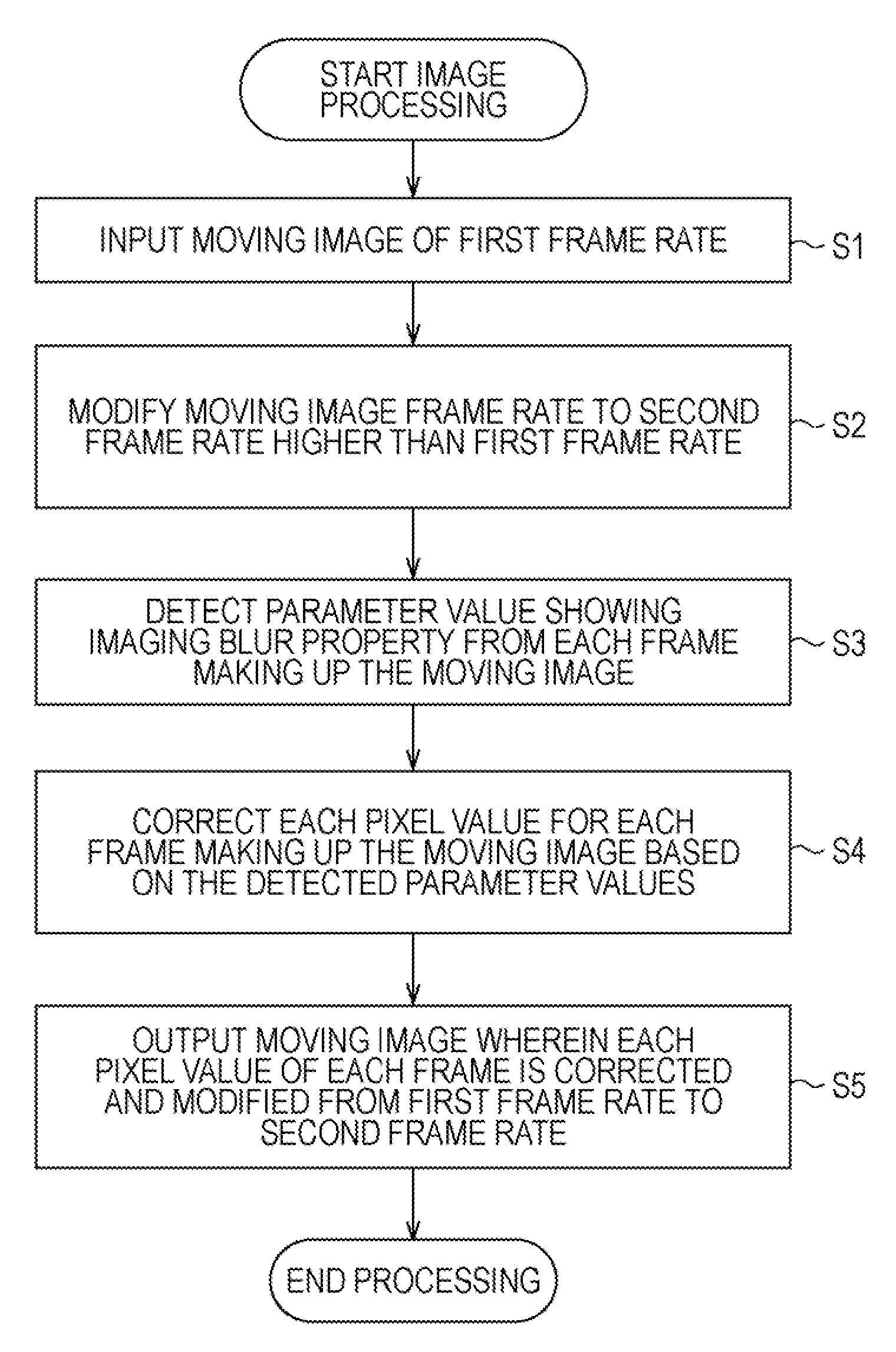
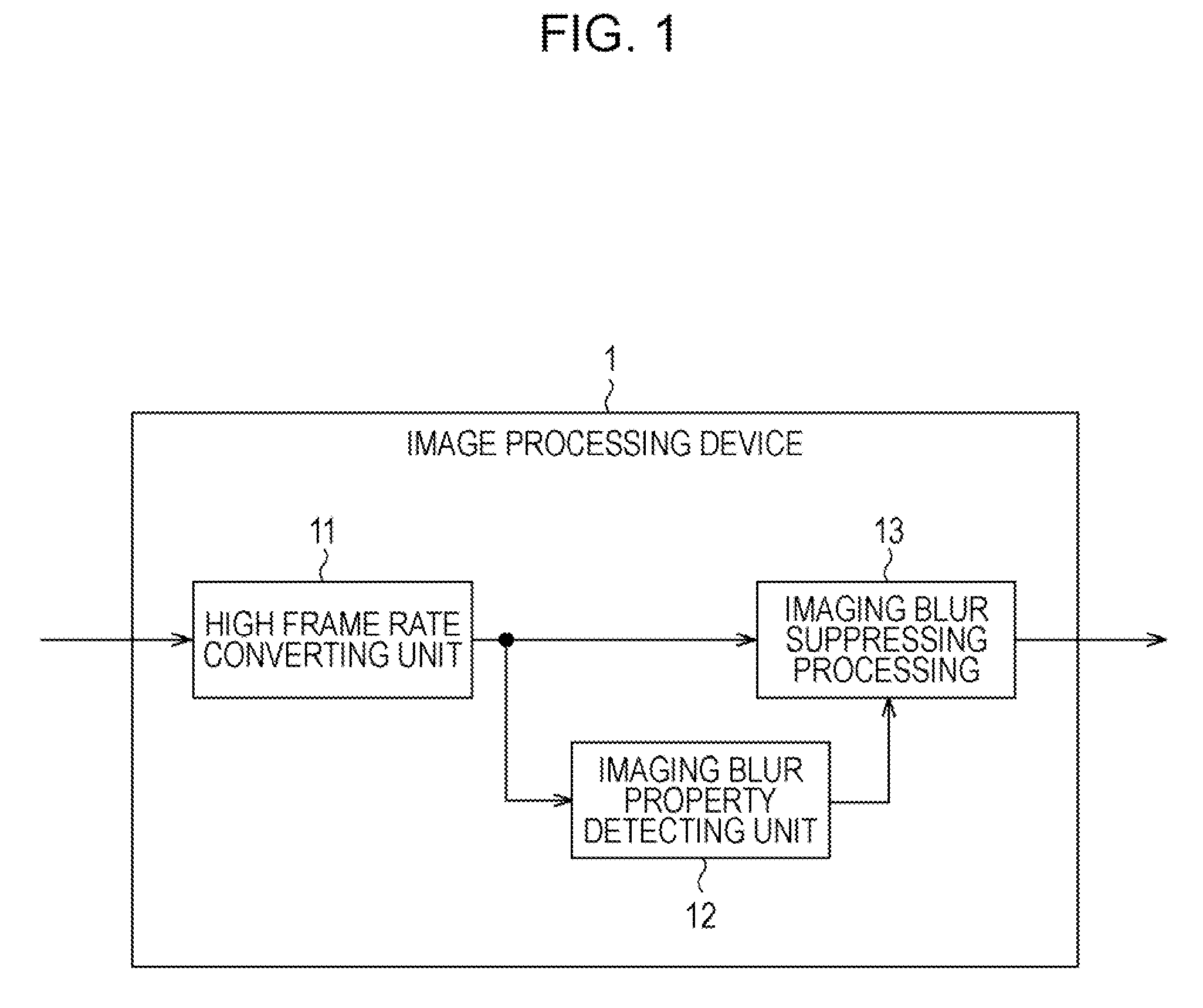
[0007]It has been realized that there is demand for enabling of displaying video after frame rate conversion more clearly by suppressing the image deterioration (blurred image) resulting from the imaging blur.
[0008]Note that even with the image processing device invented by the present inventor and disclosed previously in Japanese Unexamined Patent Application Publication No. 2006-081150, video after frame rate conversion can by displayed more clearly by suppressing image deterioration resulting from imaging blur (blurred image). Thus, the present invention enables displaying video after frame rate conversion more clearly by suppressing image deterioration with greater accuracy, while further suppressing image failure occurring from noise emphasis.
[0015]As described above, according to the present invention, image deterioration resulting from imaging blur (blurred image) can be suppressed. In particular, a moving image after frame rate conversion can be displayed more clearly by further suppressing image failure occurring from noise emphasis, while further suppressing image deterioration resulting from imaging blur (blurred image).

Problems solved by technology

Thus, image deterioration (blurred image) resulting from imaging blur has remained without being specifically corrected, and as a result, displaying a clear image on a display device has been difficult.

Method used


Image

  • Image processing device and method and program
  • Image processing device and method and program
  • Image processing device and method and program

Examples


Embodiment Construction

[0031]Before describing an embodiment of the present invention, the correspondence between the features of the claims and the specific elements disclosed in an embodiment of the present invention will be discussed below. This description is intended to assure that an embodiment supporting the claimed invention is described in this specification. Thus, even if an element in the following embodiment is not described as relating to a certain feature of the present invention, that does not necessarily mean that the element does not relate to that feature of the claims. Conversely, even if an element is described herein as relating to a certain feature of the claims, that does not necessarily mean that the element does not relate to other features of the claims.

[0032]Furthermore, this description should not be construed as restricting that all the aspects of the invention disclosed in the embodiment are described in the claims. That is, the description does not deny the existence of aspe...


PUM


Abstract

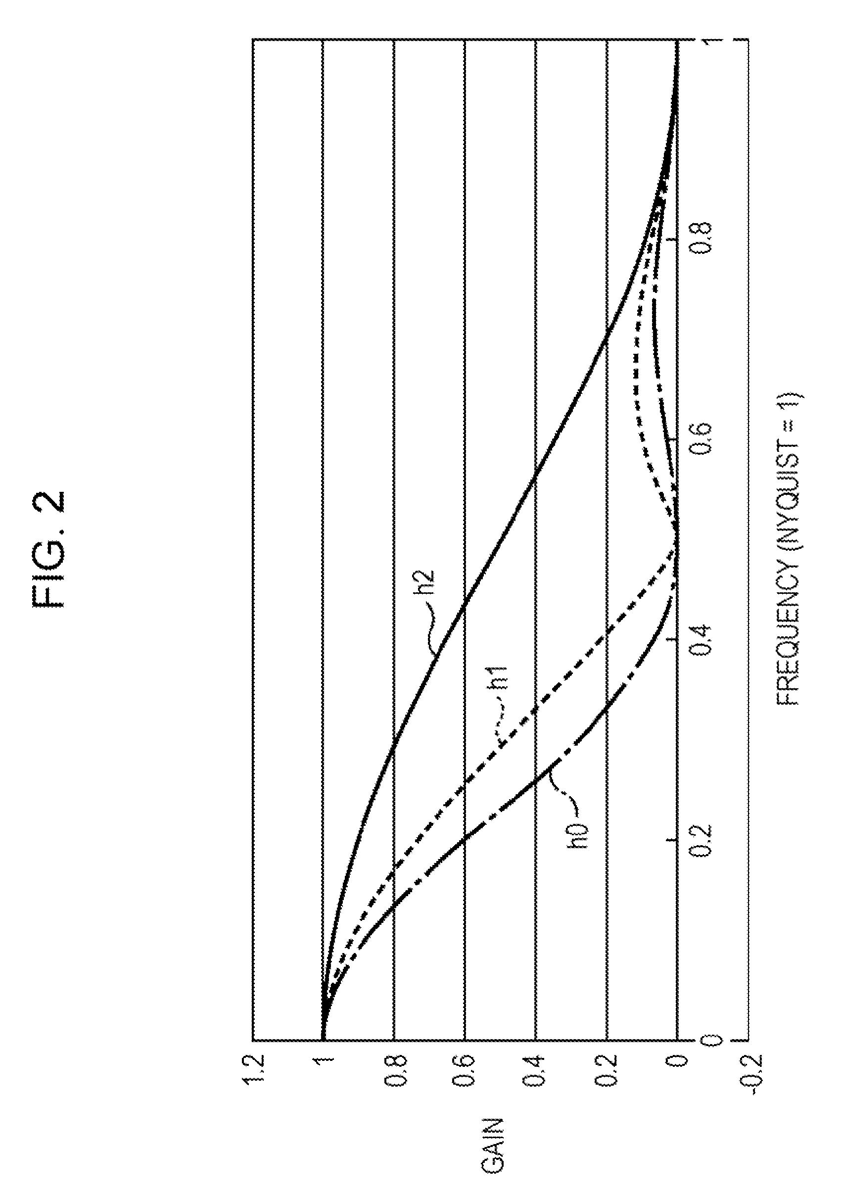
An image processing device to process a moving image, which is shot by a video shooting device, in increments of access units, includes: a correcting unit to correct the access unit to be processed by changing the properties of a low-pass filter which indicates imaging blur according to parameter values showing the properties of imaging blur which occurs at the time that the moving image is shot with the video shooting device, generating an inverse filter having inverse properties as to the low-pass filter, and performing processing to apply the inverse filters as to the access unit to be processed; wherein, with a frequency of which the frequency property of the low-pass filter indicating the imaging blur is zero being zero points, performing processing to apply the inverse filter is forbidden for predetermined frequency components of the frequency components of the access unit to be processed including the zero points.

Description

CROSS REFERENCES TO RELATED APPLICATIONS[0001]The present invention contains subject matter related to Japanese Patent Application JP 2007-260841 filed in the Japanese Patent Office on Oct. 4, 2007, the entire contents of which are incorporated herein by reference.BACKGROUND OF THE INVENTION[0002]1. Field of the Invention[0003]The present invention relates to an image processing device and method and program, and particularly relates to an image processing device and method and program wherein a video after frame rate conversion can be displayed more clearly by suppressing image deterioration (blurred image) which results from imaging blurring.[0004]2. Description of the Related Art[0005]In recent years, with a video signal conversion device for displaying video (moving image), even in a case that the frame or field frequency between an input side television method and output side television method does not have a constant synchronous relation, a method has been considered to adjust...

Claims


Application Information

Patent Timeline
IPC IPC(8): G06K9/40
CPCG06T2207/10016G06T2207/20201H04N5/23248G06T5/20H04N5/23267H04N7/0127G06T5/003H04N5/23254H04N23/6811H04N23/683H04N23/68G06T5/73
Inventor NISHI, TORUUEDA, KAZUHIKOASANO, MITSUYASU
Owner SONY CORP
Learn More