
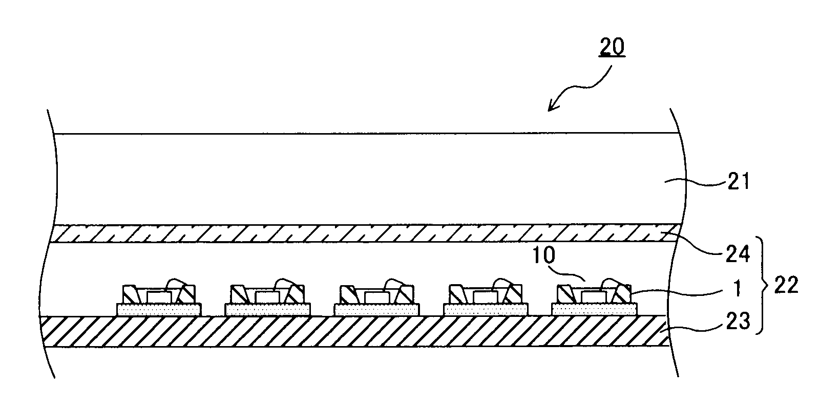
Light-emitting device, backlight using same, and liquid crystal display

Inactive Publication Date: 2009-04-16
KK TOSHIBA +1
View PDF14 Cites 19 Cited by
  • Summary
  • Abstract
  • Description
  • Claims
  • Application Information

AI Technical Summary

Benefits of technology

[0008]According to an aspect of the present invention, there are provided a light-emitting device that emission luminance can be improved without degrading the productivity and reliability, a backlight using the light-emitting device, and a liquid crystal display.

Problems solved by technology

The conventional light-emitting device having the LED element and the reflector disposed on the substrate has a drawback that emission luminance tends to become low.
In other words, since the conductive wires extended from the electrodes of the LED element are connected to the terminals on the substrate, the reflector cannot be approached enough to the periphery of the LED element.
But, since this method forms a connection point of the conductive wire outside of the reflector, the same portion cannot be used effectively for other usages.
In addition, since the conductive wires must be disposed over the top of the reflector, the conductive wires become long, and the productivity and reliability of the light-emitting device are lowered.
But, such a method causes further lowering of the emission luminance because the content of the phosphor is decreased.

Method used


Image

  • Light-emitting device, backlight using same, and liquid crystal display
  • Light-emitting device, backlight using same, and liquid crystal display
  • Light-emitting device, backlight using same, and liquid crystal display

Examples


examples 1 through 5

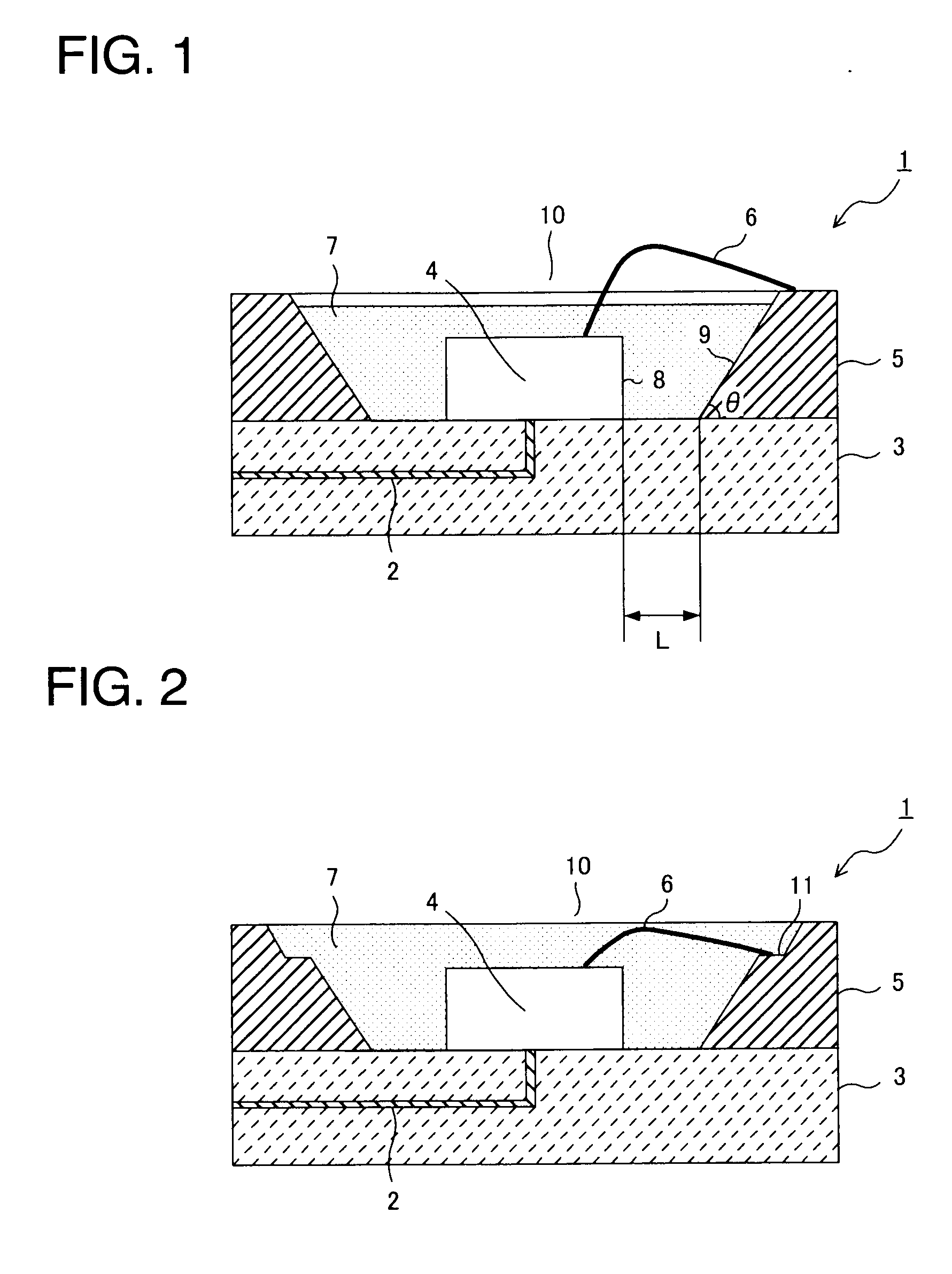
[0050]In Examples 1 through 5, the light-emitting device 1 of a white light-emitting type shown in FIG. 1 was produced. First, an aluminum nitride substrate 3 (5 mm high×5 mm wide×0.5 mm thick) having the internal wiring 2 shown in FIG. 1 was prepared. On the surface of the aluminum nitride substrate 3, a portion (including the exposed part of the internal wiring) to which an ultraviolet LED element 4 was bonded was gold-plated, and the light-emitting diode (UV-LED element) 4 (0.3 mm long×0.3 mm wide×0.3 mm high) for emitting ultraviolet light was bonded to that surface portion.

[0051]A reflector 5 (1 mm high, reflecting surface angle (θ) 45°) formed of silver-plated oxygen-free copper was bonded onto the aluminum nitride substrate 3 to surround the UV-LED element 4. The reflector 5 was used in plural types such that its distance (L) to the UV-LED element 4 fell in a range of 0.6 to 1.4 mm (Examples 1 through 5). The UV-LED element 4 and the reflector 5 was electrically connected by ...

examples 11 through 15

[0060]The white light-emitting device 1 (the distance (L) between the UV-LED element 4 and the reflector 5=0.8 mm) of Example 2 was used in quantity of 10 with the angle (θ) of the reflecting surface 9 of the reflector 5 varied in a range of 10° to 70° as shown in Table 3 to produce side light type backlights. The side light type backlights were evaluated for the presence or not of the uneven luminance and the emission luminance. The obtained results are shown in Table 3. The uneven luminance and the emission luminance were evaluated in the same manner as in Examples 6 through 10. The side light type backlights each were produced with the ten white light-emitting devices uniformly arranged at equal intervals.

TABLE 3Angle [θ] ofreflectingPresence ofsurface ofunevenEmissionreflectorluminanceluminanceExample 1170°AAExample 1260°AAExample 1345°AAExample 1435°AAExample 1510°AB

[0061]It is apparent from Table 3 that the side light type backlight has no occurrence of uneven luminance regard...


PUM


Abstract

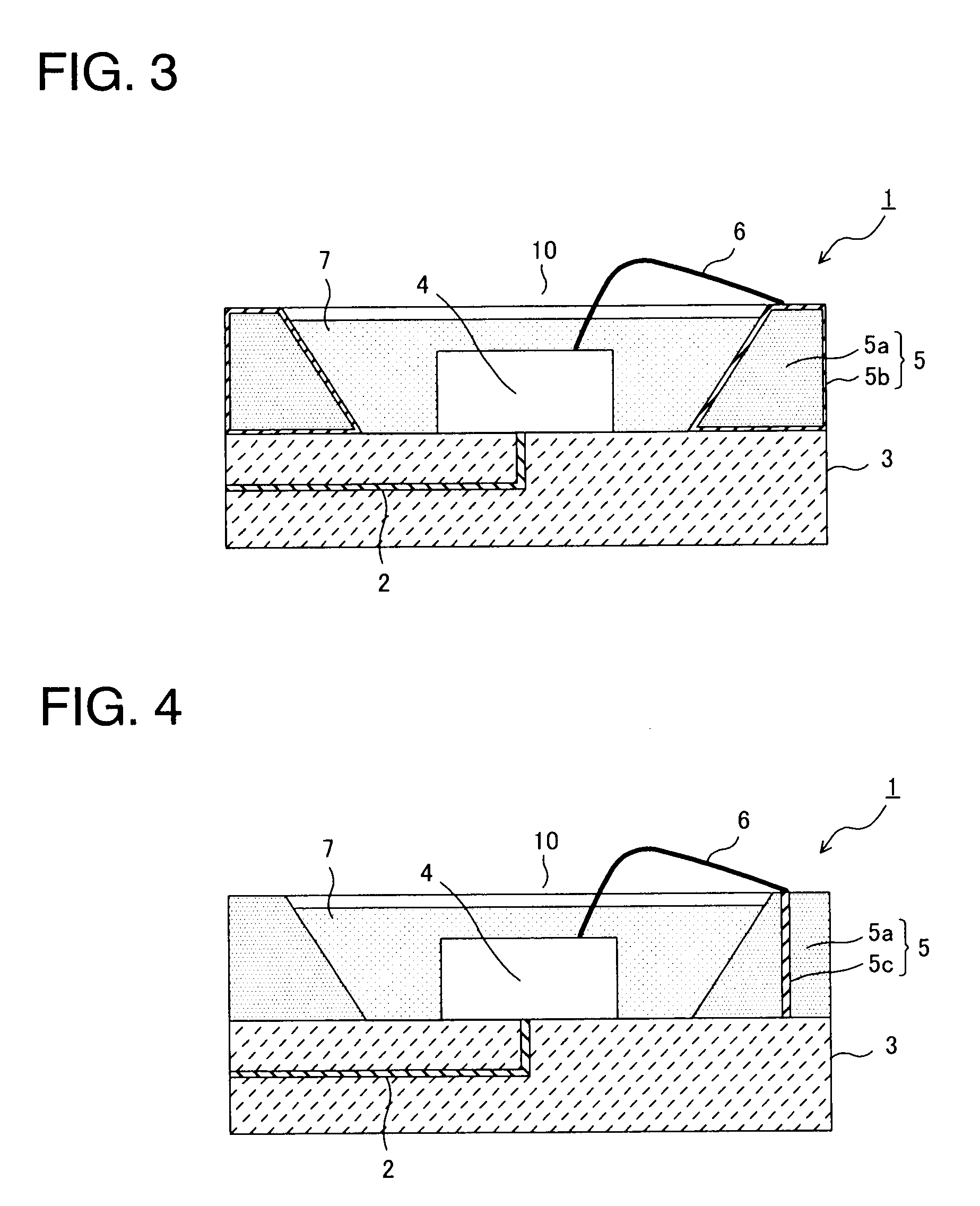
A light-emitting device includes a semiconductor light-emitting element arranged on a substrate having internal wiring, a reflector arranged around the semiconductor light-emitting element, and a light-emitting portion, filled in the reflector, having a phosphor which emits visible light when excited by light from the semiconductor light-emitting element. Electrical conduction to the light-emitting element is obtained via the internal wiring of the substrate and the reflector.

Description

TECHNICAL FIELD[0001]The present invention relates to a light-emitting device, a backlight using it, and a liquid crystal display.BACKGROUND ART [0002]A light emitting diode (LED) is a semiconductor element converting electrical energy into light such as ultraviolet light, visible light or the like, and has advantages that it has a long life and high reliability, and when the LED is used as a light source, the time which exchanges lamps can be saved. A light-emitting device (LED lamp) having an LED element sealed with, for example, a transparent resin is used extensively as a component part for various types of displays such as portable communication devices, PC peripheral devices, office automation equipment, home electric appliances, signal equipment, various types of switches, backlight type display panels, and the like.[0003]For example, the light-emitting device using the LED element has a structure that the LED element is fixed onto a substrate and each of electrodes of the LE...

Claims


Application Information

Patent Timeline
IPC IPC(8): G02F1/13357H01J1/62H01L33/60H01L33/62
CPCH01L33/60H01L33/62H01L2224/48091H01L2924/01025H01L2924/01057H01L2924/01322H01L2924/01078H01L2924/01079H01L2924/01063H01L2924/01019H01L2924/00014
Inventor OOYA, YASUMASASAKAI, RYOTAKEUCHI, HAJIMEISHII, TSUTOMUSHIRAKAWA, YASUHIRO
Owner KK TOSHIBA
Learn More