
Hand position detecting device and apparatus including the device

a technology of hand position and detecting device, which is applied in the direction of instruments, horology, electric winding, etc., can solve the problems of inaccurate detection of inability to accurately detect three kinds of detection patterns, and inability to accurately determine the rotational position of the center and hour hands, etc., and achieve the effect of short time and accurate determination

Active Publication Date: 2009-04-02
CASIO COMPUTER CO LTD
View PDF11 Cites 20 Cited by
  • Summary
  • Abstract
  • Description
  • Claims
  • Application Information

AI Technical Summary

Benefits of technology

[0014]According to this invention, when the center wheel is rotated one step at a time in the predetermined direction to the position where the apertures in the center and intermediate wheels align and the aperture detecting means detects light, the position of the center is presumed to be its reference position. It is necessary to ascertain that it is really the reference position. To this end, the center wheel is returned a predetermined number of steps or more necessary for the center wheel to move substantially completely away from the position where the aperture detecting means detected light. Then, the center wheel is further rotated one step at a time in the predetermined direction to the position where the aperture detecting means detected the light, thereby causing the aperture detecting means to try to detect light again at the position. If the aperture detecting means detects the light again, the position of the aperture in the center wheel is determined as the predetermined position in the center wheel. Thus, even if the center and intermediate wheels contain assembling or manufacturing errors, the position of the center hand is determined accurately in a short time without being misunderstood.

Problems solved by technology

However, it takes a considerable time to detect these patterns.
In addition, these three kinds of detection patterns can not be detected accurately depending on the manufacturing accuracy of the light blocking areas of the center and hour wheels, and the assembling accuracy of the third, center and hour wheels.
Thus, the rotational positions of the center and hour hands can be misunderstood.

Method used


Image

  • Hand position detecting device and apparatus including the device
  • Hand position detecting device and apparatus including the device
  • Hand position detecting device and apparatus including the device

Examples


Embodiment Construction

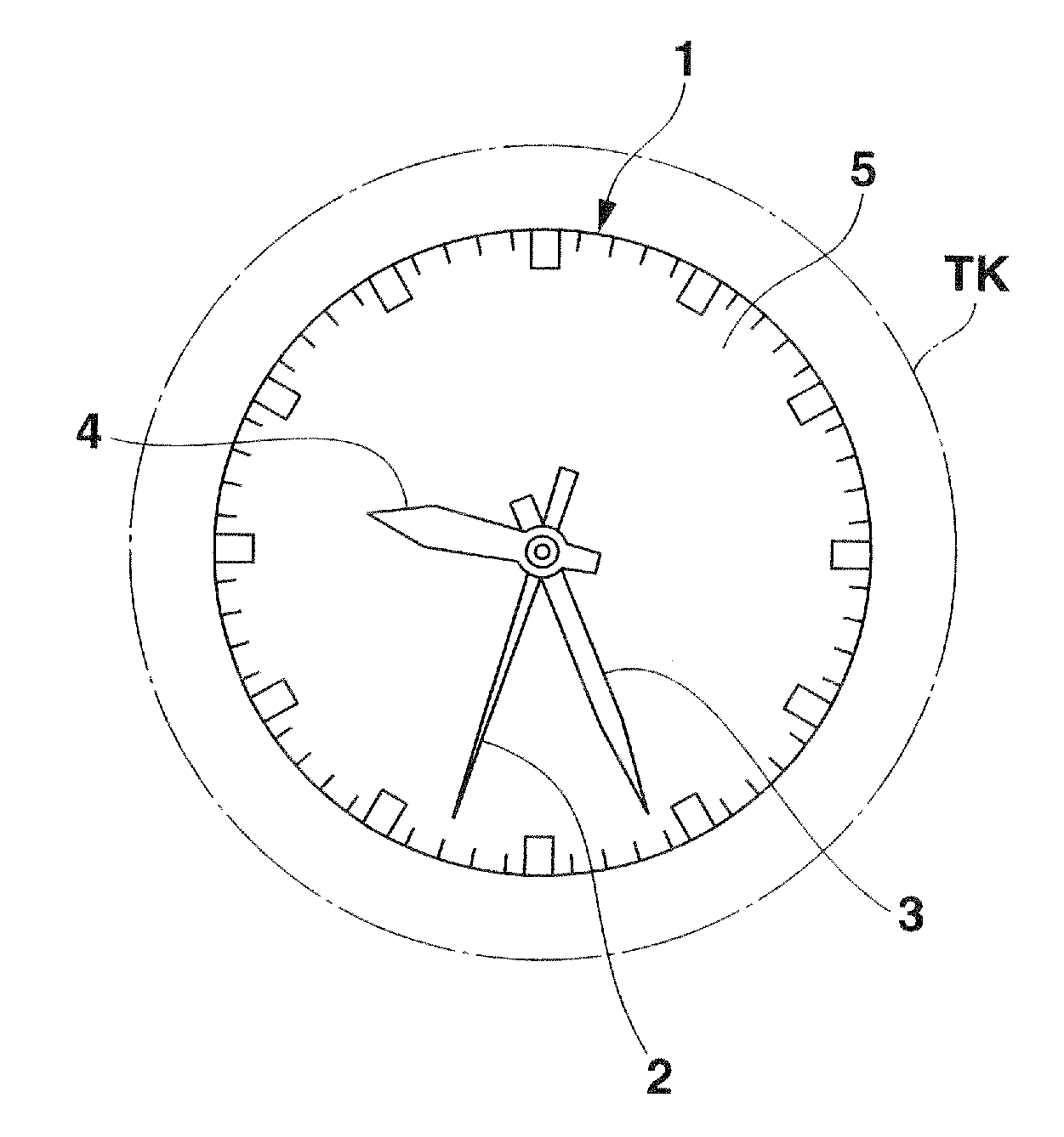
[0044]Referring to FIGS. 1 to 25, description will be made of a hand type wristwatch according to one embodiment of the present invention. This wristwatch comprises a watch module 1 of FIGS. 1 and 2, which in turn comprises a seconds hand 2, a center hand 3 and an hour hand 4 which sweep around a dial 5 to indicate time and is encased within a case TK with glass G on top of the case and with a case back UB.

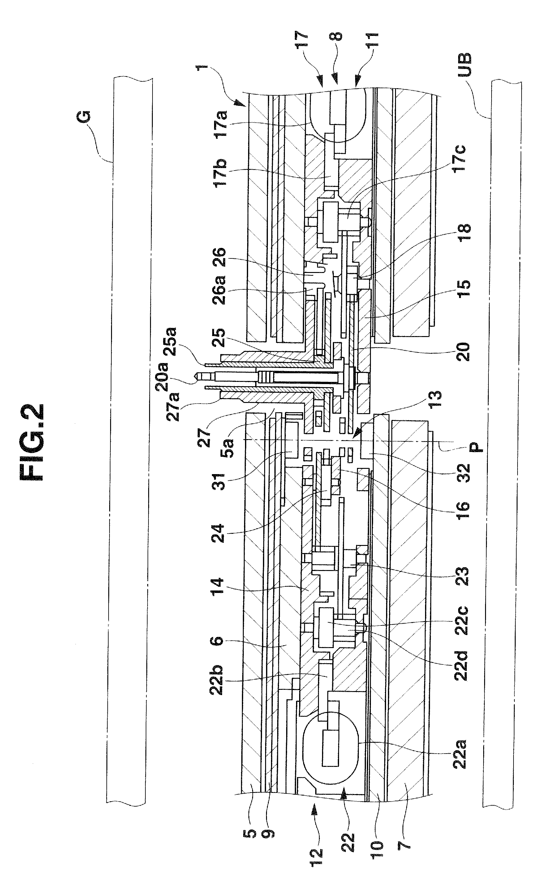
[0045]As shown in FIG. 2, the watch module 1 has an upper housing 6 and a lower housing 7 between which a watch movement 8 is provided. The dial 5 is provided on top of the upper housing 6 through a solar panel 9. A circuit board 10 is provided within the lower housing 7.

[0046]As shown in FIGS. 2 to 4, the watch movement 8 comprises a first driving system 11 which drives the seconds hand 2 and a second driving system 12 which drives the center and hour hands 3 and 4, and a detection unit 13 that detects the rotational positions of the seconds, center and hour hands 2, 3 and 4. The...


PUM


Abstract

It is determined whether light has passed through apertures in a seconds, a center and an intermediate wheels and a relevant one of apertures in an hour wheel, thereby determining their respective rotational positions. When the center wheel rotates one step at a time in a predetermined direction to such a position that the apertures in the center and intermediate wheels align and a detection unit detects light which has passed thorough the apertures, the center wheel is returned twelve steps or more in the reverse direction. The center wheel is again rotated one step at a time in the predetermined direction to the position where the detection unit detected light first. When the detection unit again detects light at that position, this position is determined as the reference position in the center wheel.

Description

CROSS-REFERENCE TO RELATED APPLICATIONS[0001]This application is based upon and claims the benefit of priority from the prior Japanese Patent Application No. 2007-253536, filed on Sep. 28, 2007, the entire contents of which are incorporated herein by reference.BACKGROUND OF THE INVENTION[0002]1. Field of the Invention[0003]The present invention relates to a hand position detecting device which detects the rotational positions of seconds, center and hour hands and electronic apparatus including the detecting device.[0004]2. Description of the Related Art[0005]In the past, a hand position detecting device which detects the rotational positions of hands of a timepiece is known, as disclosed by Japanese Published Unexamined Application 2000-162336. This device comprises a first drive system in which a first drive motor transmits its rotation to a seconds wheel which in turn causes a seconds hand to sweep around a dial, a second drive system in which a second drive motor transmits its ro...

Claims


Application Information

Patent Timeline
IPC IPC(8): G04B47/00G01B11/14
CPCG04C3/14G04D7/04
Inventor AOKI, NOBUHIRO
Owner CASIO COMPUTER CO LTD
Learn More