
Inkjet printer

a printer and inkjet technology, applied in the direction of printing, other printing apparatus, etc., can solve the problems of deteriorating paper pickup efficiency, stuffy atmosphere of paper output tray, etc., and achieve the effect of increasing paper pickup efficiency, reducing paper pickup times, and increasing paper pickup efficiency

Inactive Publication Date: 2009-04-02
NORITZ CORP
View PDF3 Cites 17 Cited by
  • Summary
  • Abstract
  • Description
  • Claims
  • Application Information

AI Technical Summary

Benefits of technology

[0010]The present invention has been made in view of the foregoing points and, therefore, an object thereof is to provide an inkjet printer by which the operator has no need to pick up printed pieces of paper in an unpleasant ambience full of dry air for drying the pieces of paper and can pick up them comfortably.
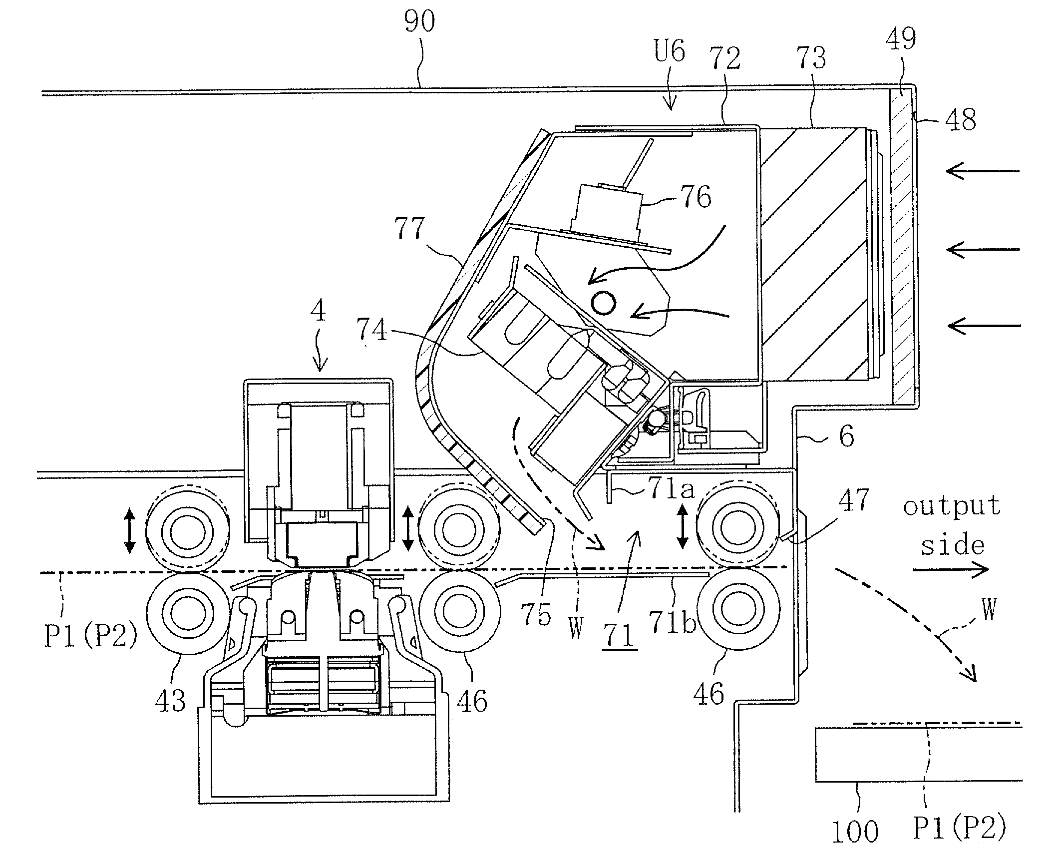
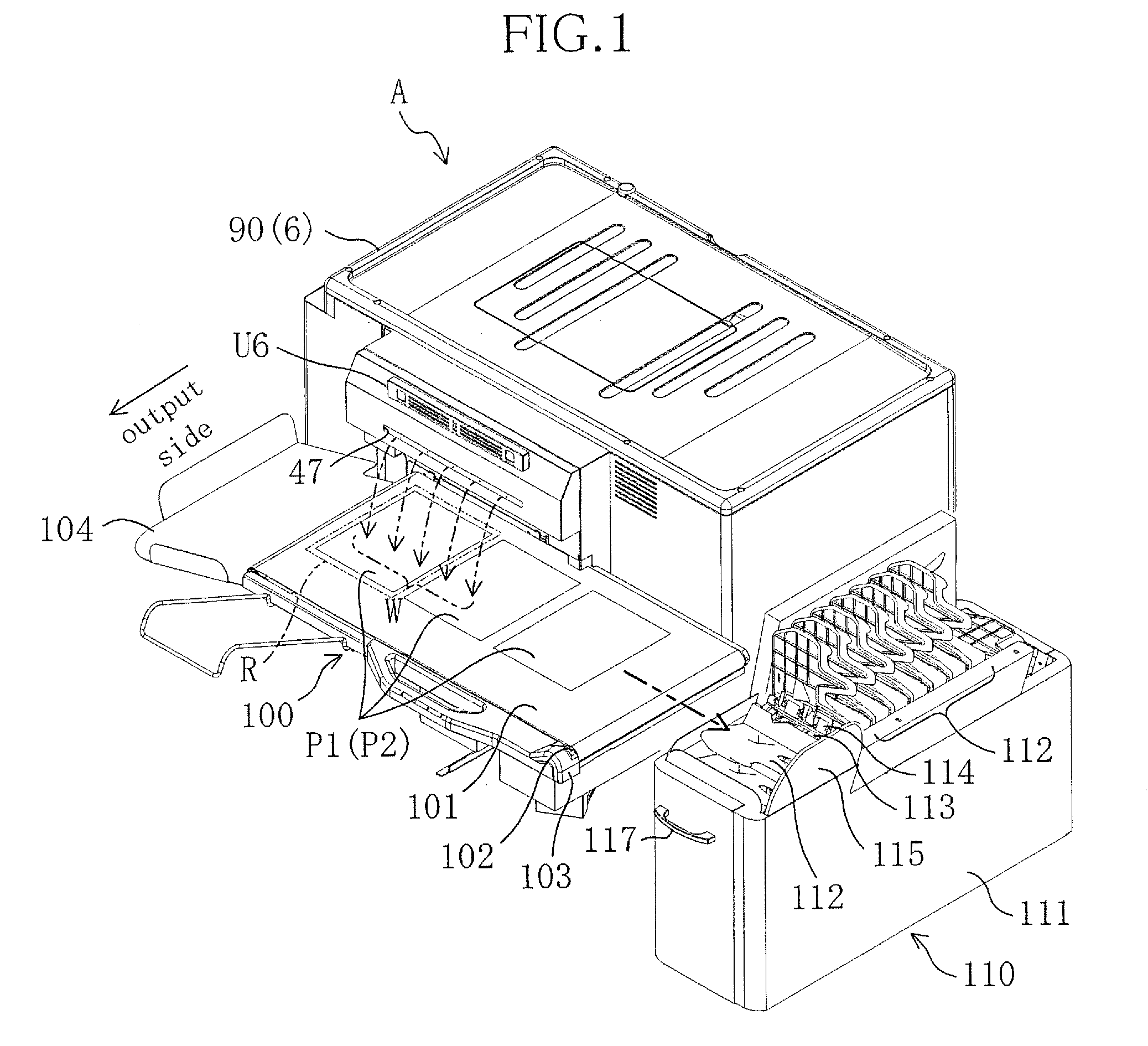
[0011]To attain the above object, in the present invention, a placement device for laying printed pieces of paper thereon is configured to convey the pieces of paper in a direction substantially orthogonal to a direction of paper output, whereby the pieces of paper can be conveyed to a location kept away from the unpleasant ambience full of dry air and the operator can pick up the pieces of paper under a comfortable environment.
[0014]As described above, the paper laid on the placement device is conveyed by the placement device in the direction substantially orthogonal to the direction of paper output and collected by the collecting device located downstream in the direction of paper conveyance. Therefore, even if dry air in the drying device is blown out to the placement device so that a stuffy unpleasant ambience full of dry air is formed above the placement device, the space around the collecting device where the operator picks up the printed paper is kept away from the unpleasant ambience. This eliminates the need for the operator to pick up the paper in the unpleasant ambience and provides a comfortable paper pickup work, thereby increasing the paper pickup efficiency.
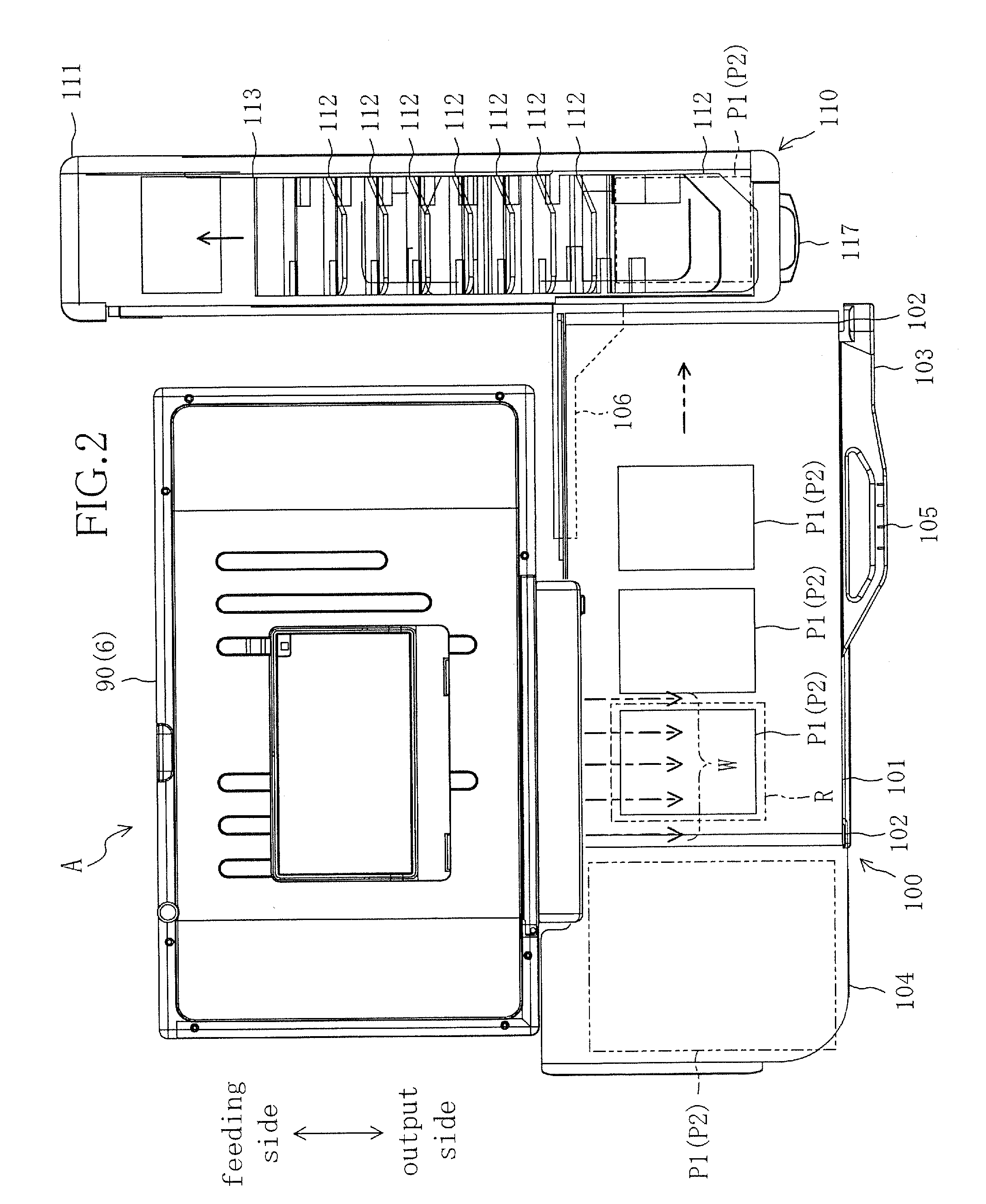
[0017]Since the collecting device conveys the collected paper in the direction substantially orthogonal to the direction of paper conveyance of the placement device, the printed paper can be conveyed towards the paper feeding side of the inkjet printer and the operator can pick up the paper on the paper feeding side opposite to the unpleasant ambience existing on the paper output side of the inkjet printer and full of dry air, which increases the paper pickup efficiency. More specifically, in a common inkjet printer, an ink tank and a roll of paper web are disposed on the paper feeding side thereof. If the printed paper is conveyed to a region used for maintenance, such as replacement of ink or a roll of paper web, the operator can carry out the maintenance and paper pickup works at the same location as the location for paper feeding, without the need to move from the maintenance space to the paper pickup space in order to pick up the paper, and can carry out these necessary works at a location opposite to the unpleasant ambience. This provides a comfortable and efficient paper pickup work.
[0019]Since a plurality of pieces of paper are divided in units of print orders by the plurality of collecting plates provided in the collecting device, the operator does not need to manually assort the pieces of paper in units of print orders. Furthermore, if a given number of pieces of paper are printed and then picked up at a time, the number of paper pickup times can be reduced, which increases the paper pickup efficiency.
[0020]As described so far, according to the inkjet printer of the present invention, the paper laid on the placement device is conveyed by the placement device in the direction substantially orthogonal to the direction of paper output and collected by the collecting device located downstream in the direction of paper conveyance. Therefore, even if dry air in the drying device is blown out to the placement device so that a stuffy unpleasant ambience full of dry air is formed above the placement device, the working space around the collecting device where the operator picks up the printed paper is kept away from the unpleasant ambience. This eliminates the need for the operator to pick up the paper in the unpleasant ambience and provides a comfortable paper pickup work, thereby increasing the paper pickup efficiency.

Problems solved by technology

Therefore, dry air resides on the paper output tray to form above the paper output tray a stuffy unpleasant ambience in which heat and moisture reside.
The operator must pick up, in such an unpleasant ambience, printed pieces of paper laid on the paper output tray, which may deteriorate the paper pickup efficiency.

Method used


Image

  • Inkjet printer
  • Inkjet printer
  • Inkjet printer

Examples


Embodiment Construction

[0031]A description is given below of an embodiment of the present invention with reference to the drawings. The following preferred embodiment is merely illustrative in nature and is not intended to limit the scope, applications and use of the invention.

[0032]FIG. 1 is a perspective view showing the appearance of an inkjet printer A according to an embodiment of the present invention, FIG. 2 is a plan view of the inkjet printer A, FIG. 3 is a front view thereof, FIG. 4 is a left side view thereof and FIG. 5 is a schematic view thereof as viewed from the left of a housing, showing a conveyance path of printing paper. The inkjet printer A is used for a photographic printing system and, for example, used for printing photographic images on printing paper P1 or P2 based on image data transmitted via a communication cable from a reception block for obtaining the image data and correcting it as necessary. More specifically, the inkjet printer A is configured to be capable of performing a...


PUM


Abstract

In an inkjet printer configured so that dry air in a drying unit is blown out to a conveyance unit, the conveyance unit conveys one or more pieces of paper laid thereon in a direction substantially orthogonal to a direction of paper output and a collecting unit downstream of the conveyance unit in the direction of paper conveyance collects the pieces of paper and conveys the collected pieces of paper in a direction substantially orthogonal to the direction of paper conveyance of the conveyance unit.

Description

CROSS-REFERENCE TO RELATED APPLICATION[0001]This application claims priority under 35 USC 119 to Japanese Patent Application No. 2007-251540 filed on Sep. 27, 2007, the entire contents of which are incorporated herein by reference.BACKGROUND OF THE INVENTION[0002](a) Field of the Invention[0003]This invention relates to inkjet printers.[0004](b) Description of the Related Art[0005]Inkjet printers are conventionally known as devices for printing characters and images (hereinafter, characters and images are generically called “images”). The inkjet printers print images on paper by reciprocal movement in the paper width direction of their print heads ejecting ink.[0006]In such an inkjet printer, if printed pieces of paper are stacked one after another on the paper output tray with ink on the pieces of paper not yet dried up, this causes inconveniences, such as a phenomenon that the ink on each piece of paper cannot uniformly be dried to cause color shading of the printed images or a ph...

Claims


Application Information

Patent Timeline
IPC IPC(8): B41J2/01
CPCB41J11/002B41J11/0022
Inventor SAKAMOTO, KENICHI
Owner NORITZ CORP
Learn More