
Method for mapping write operation of raid device

Inactive Publication Date: 2009-03-26
INVENTEC CORP
View PDF2 Cites 2 Cited by
  • Summary
  • Abstract
  • Description
  • Claims
  • Application Information

AI Technical Summary

Benefits of technology

[0017]Based on the above, the present invention has the following advantages.
[0018](1) The method of the present invention ensures the integrity and safety of the data stored in the RAID device and prevents the data from being lost when the member disk of the RAID device is replaced or severely damaged;
[0019](2) The method of the present invention ensures the robustness of the RAID device, and the data of the whole RAID device is not affected by the damage of a single member disk of the RAID device; and

Problems solved by technology

If a problematic sector exists in the disk, the RAID device considers the disk to be damaged, so as to get into a degrading or damaging mode, such that the RAID device cannot be used any more.
It is a great loss for the user that the whole RAID device cannot be used due to the damage of merely one or a few sectors of the disk.
However, the single disk fault-tolerance mechanism in the conventional art cannot come into effect in the RAID device capable of performing a rebuild operation, which can merely protect the data of a single disk, instead of ensuring the integrity of the whole data in the RAID device.

Method used


Image

  • Method for mapping write operation of raid device
  • Method for mapping write operation of raid device
  • Method for mapping write operation of raid device

Examples


Embodiment Construction

[0028]In order to make the aforementioned and other objectives, features and advantages of the present invention be more comprehensible, preferred embodiments accompanied with figures are described in detail below.

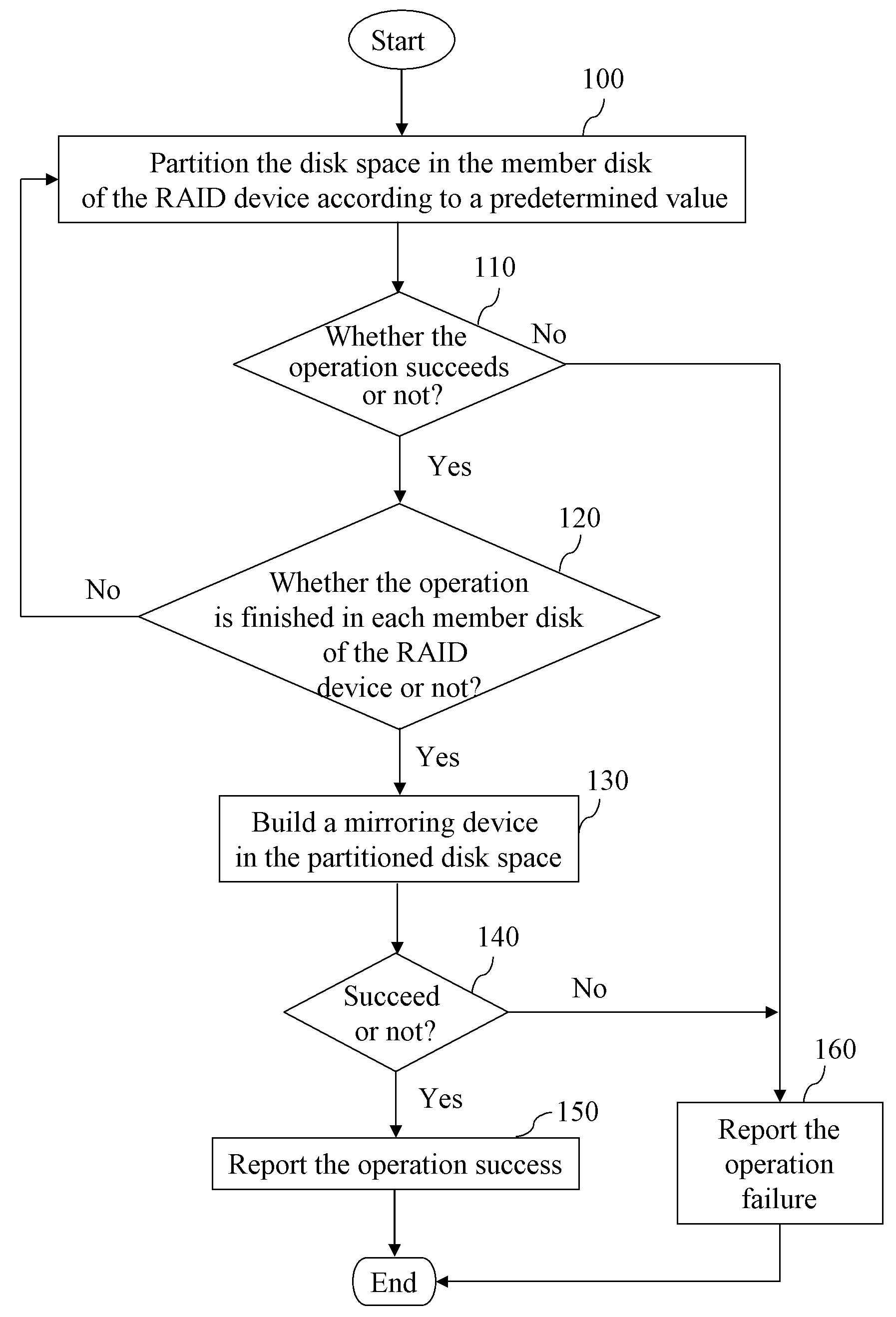
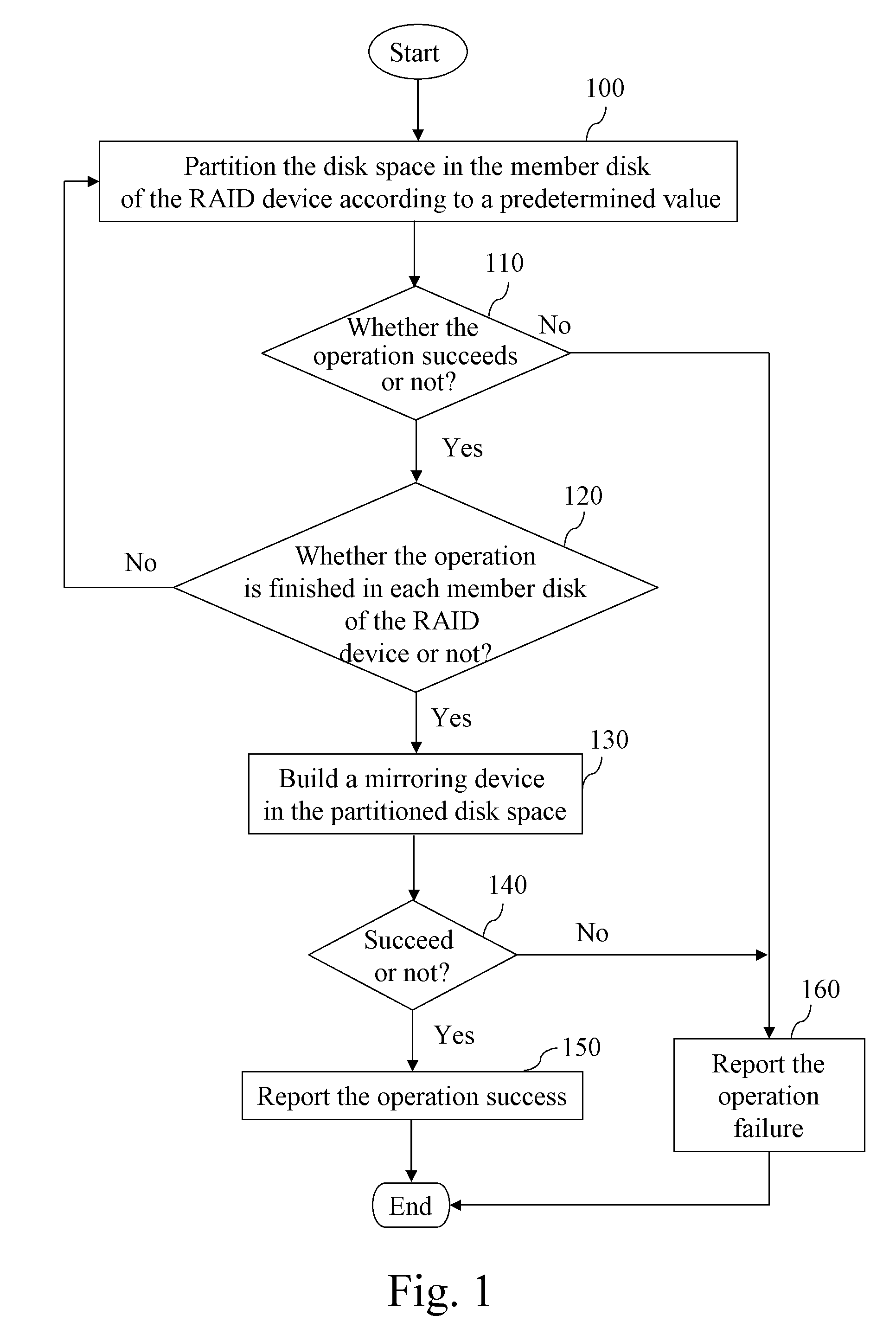
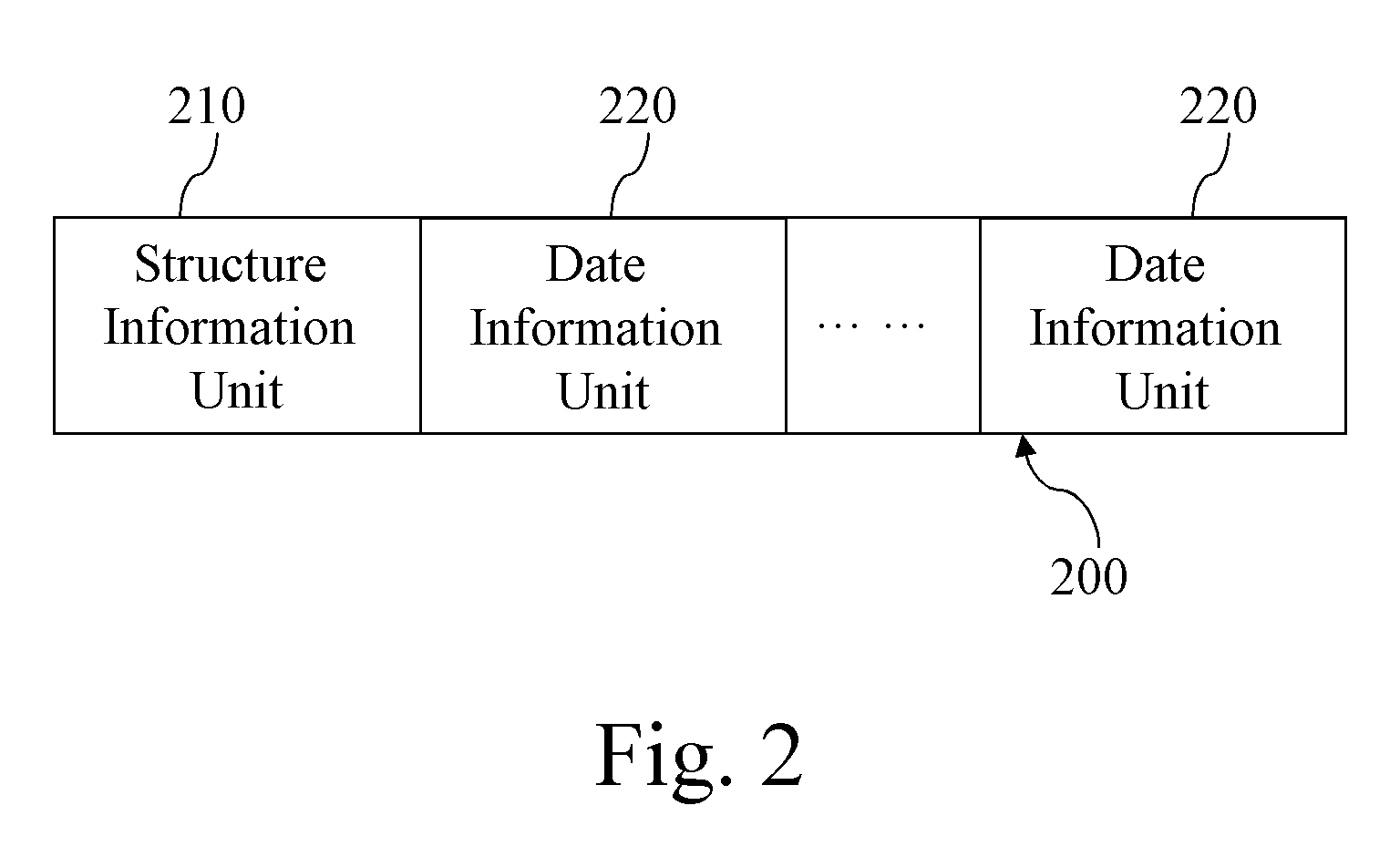
[0029]FIGS. 1 and 2 show a process of initiating a mirroring device 200 and a structure of the initiated mirroring device 200 according to the present invention. The mirroring device 200 is built in each member disk of the RAID device in a manner of RAID-1. As shown in figures, first of all, a disk space is partitioned for the mirroring device 200 in the member disk of the RAID device according to the predetermined value (Step 100). The predetermined value is preferably 5%. During the usage, if the data to be mapped exceeds the storage capacity of the mirroring device 200, the system informs the user that the mirroring device 200 cannot be used normally, but the data-reading operation still can be executed. It is determined whether the operation of partitioning the disk sp...


PUM


Abstract

A method for mapping a write operation of an RAID device, includes flowing steps, initiating a mirroring device built in each member disk of the RAID device; activating a kernel thread, for monitoring the operation state of the RAID device, and recording current usage information; and if an incorrect write operation occurs to a member disk of the RAID device, storing the data of the incorrect write operation into a mirroring device of another member disk of the RAID device through the kernel thread. The method ensures the integrity and safety of the data stored in the RAID device and prevents the data from being lost when the member disk of the RAID device is replaced or severely damaged.

Description

BACKGROUND OF THE INVENTION[0001]1. Field of the Invention[0002]The present invention relates to a disk management method, and more particularly to a method for mapping a write operation of a redundant arrays of inexpensive disks (RAID) device.[0003]2. Related Art[0004]The redundant arrays of inexpensive disks (RAID) device combines N disks into a virtual single disk of a large capacity through an RAID controller (hardware or software), so as to provide a large storage capacity, a high accessing speed, or a data redundant function. According to different organizing manner of the data, the RAID device includes linear RAID, RAID-0, RAID-1, RAID-5, RAID-6, etc. The RAID-1, RAID-5, RAID-6 and RAID-10, RAID-50 extended there-from all provide a data redundant function.[0005]The data redundant function means that: since RAID device stores the redundant data, if one or more disks in the RAID device are damaged, the data can be obtained completely from the RAID device through a certain proce...

Claims


Application Information

Patent Timeline
IPC IPC(8): G06F12/06
CPCG06F11/2094G06F11/1662
Inventor WANG, JIAN-FEICHEN, TOMLIU, WIN-HARN
Owner INVENTEC CORP
Learn More