
Spinal stabilization device

Active Publication Date: 2009-03-26
SPINAL ELEMENTS INC
View PDF26 Cites 124 Cited by
  • Summary
  • Abstract
  • Description
  • Claims
  • Application Information

AI Technical Summary

Benefits of technology

[0038]Provided herein is a method for implanting a spinal stabilization device comprising delivering a first bone attachment device to a first pedicle, wherein the first bone attachment device comprises a first bone fastener having a distal portion adapted to pierce bone and a proximal portion having a head, and a first collar comprising a collar wall defining a cavity and having at least one wall aperture, a distal portion comprising an opening and a collar seat projecting inward and supporting a head of the bone fastener, a proximal portion having a hinged lid, and a spinal rod locking device, wherein at least a portion of the spinal rod locking device is within the cavity defined by the collar wall. The method may further comprise fastening the distal portion of the first bone fastener to the first pedicle. In some embodiments, the method comprises delivering a second bone attachment device to a second pedicle, wherein the second bone attachment device comprises a second bone fastener having a distal portion adapted to pierce bone and a proximal portion having a head, and a second collar comprising: a collar wall defining a cavity and having at least one wall aperture; a distal portion comprising an opening and a collar seat projecting inward and supporting a head of the bone fastener; and a spinal rod locking device, wherein at least a portion of the spinal rod locking device is within the cavity defined by the collar wall. In some embodiments, the method comprises placing a rod within the aperture of the first bone attachment device. The method may further comprise placing the rod within the aperture of the second bone attachment device. In some embodiments, the method further comprises locking the first bone attachment device, wherein the locking comprises pivoting the hinged lid toward the first collar over the rod, and engaging an overhang of the first collar with a collar engagement member of the spinal rod locking device of the first collar. The method may further comprise locking the second bone attachment device. The locking steps may lock the rod in place, thereby preventing translational motion of the rod.

Problems solved by technology

While pedicle screw, rod, and coupler systems have many benefits, there remain challenges and inadequacies.
For example, the pedicle screw, coupler, and rod systems are often made up of multiple pieces which can get dropped, fumbled during surgery, or misplaced.
The multitude of pieces to a system might also mean that that several people are required to assemble and align the pieces during surgery.
Additionally, the multitude of pieces to a system can also result in a high assembled profile, which can be uncomfortable, if not painful, to a recovering patient.
A high profile system can also be disruptive to the recovered patient since the systems are seldom removed once spine fusion is complete.
Furthermore, while the polyaxial nature of the system is a benefit to final alignment, one drawback to a polyaxial screw system is that before the rod is locked down, the coupler and rod can typically move freely relative to the head of the screw as other pedicle screws are implanted and as the rod is connected to another coupler.
This makes the actual process of aligning and holding the coupler and rod in place prior to locking down all polyaxial screw systems more complicated—requiring more finesse and potentially multiple operators.
These challenges can prolong surgery time and add cost and risk to the procedure and to patient recovery.

Method used


Image

  • Spinal stabilization device
  • Spinal stabilization device
  • Spinal stabilization device

Examples


Embodiment Construction

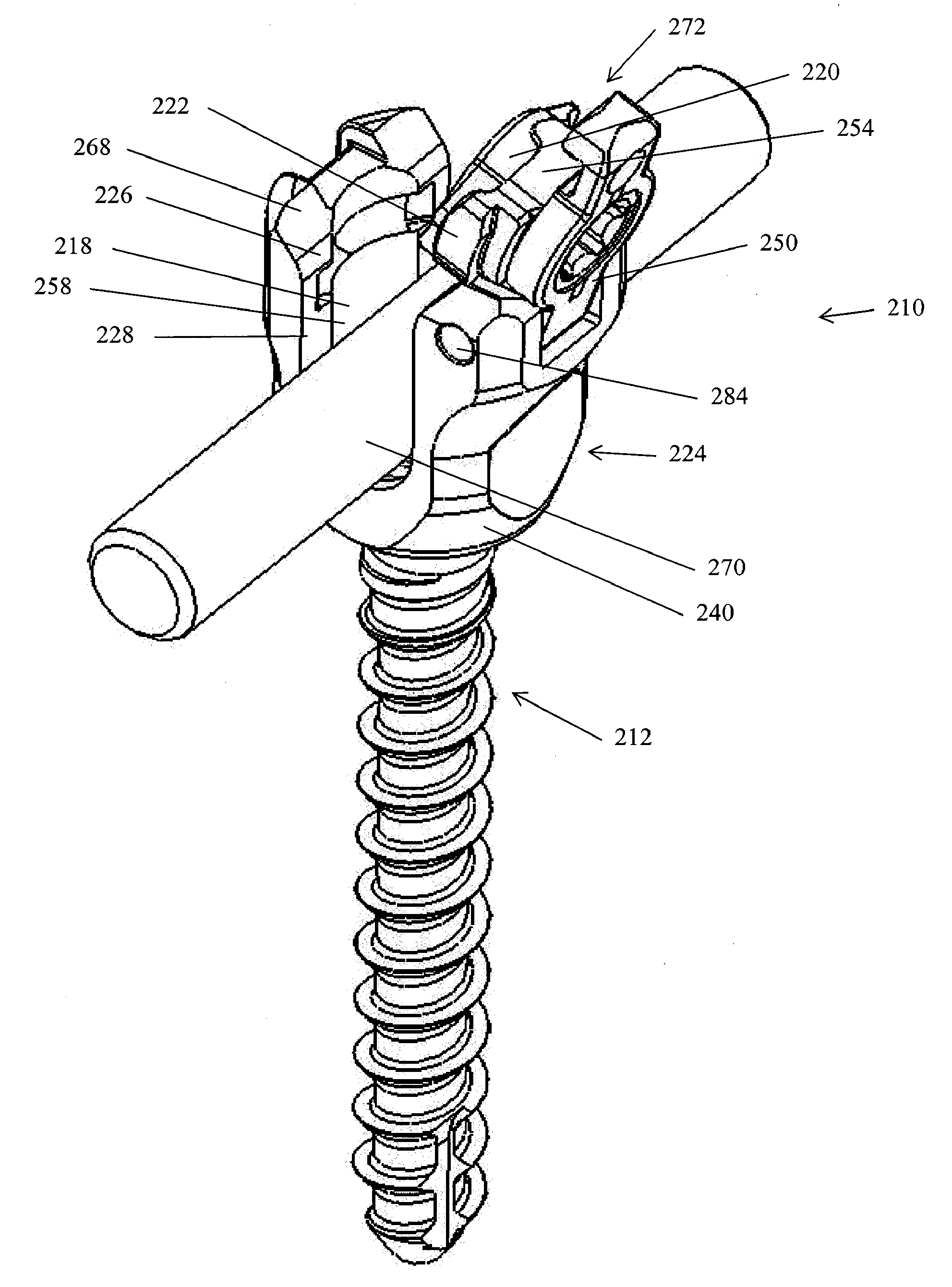
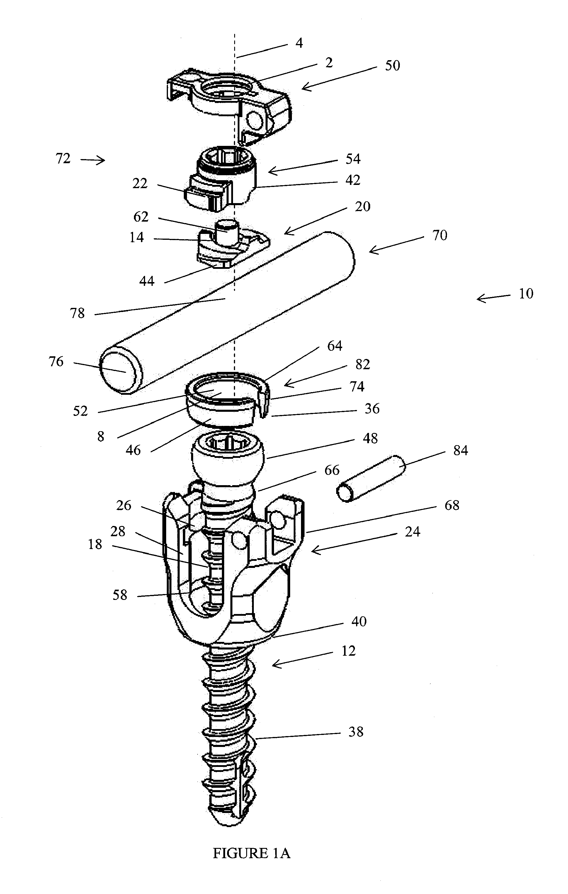
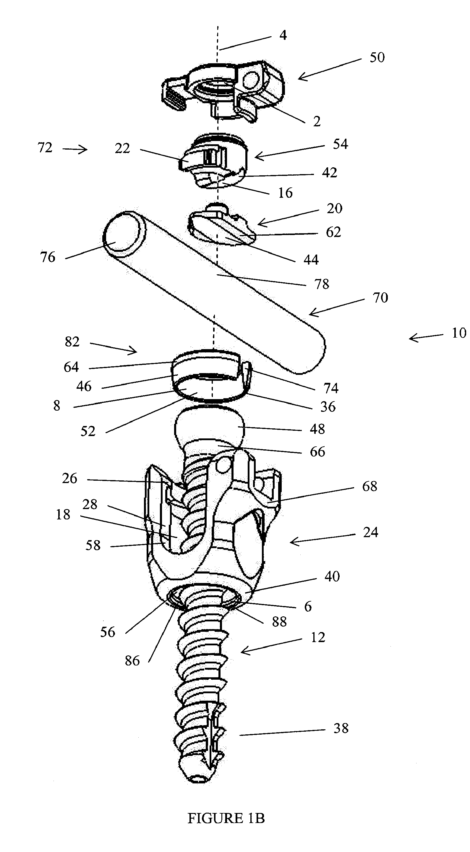
[0057]There are described herein bone attachment devices (pedicle screws) and spinal stabilization devices employing such pedicle screws. Pedicle screws described herein provide certain advantages. In some embodiments, such advantages include low profile. In some embodiments, such advantages include the convenience of providing a collar with a hinged cap, whereby the collar and the cap will not easily become separated prior to or during a surgical procedure. Other advantages and characteristics of the pedicle screws will be apparent upon consideration of the description herein and the drawings appended hereto.

[0058]Some embodiments described herein provide a bone attachment device, comprising: (a) a bone fastener having a distal portion adapted to pierce bone and a proximal portion having a head; (b) a collar comprising: (i) a collar wall defining a cavity and having at least one wall aperture; (ii) a distal portion comprising an opening and a collar seat projecting inward and suppo...


PUM


Abstract

A bone attachment device comprises an attachment collar having a hinged lid is disclosed. The bone attachment device may also comprise a bone fastener (such as a bone screw). A bone attachment device including an attachment collar and a spinal rod locking device is disclosed. A bone attachment device as described herein may be used together with a spinal stabilization rod and one or more additional bone attachment devices. Such devices are adapted to clamp and hold a spinal stabilization rod. Methods for implanting a spinal stabilizer having a bone attachment device including a hinged lid are disclosed.

Description

CROSS REFERENCE[0001]This application claims benefit of priority to U.S. provisional patent application 60 / 946,893, filed Jun. 28, 2007, which is incorporated herein in its entirety.BACKGROUND OF THE INVENTION[0002]The pedicle screw, which is sometimes used as an adjunct to spinal fusion surgery, provides a means of gripping a spinal segment. The screws themselves do not fixate the spinal segment, but act as anchor points that can then be connected with a rod. The screws are usually placed at two or three consecutive spine segments and then a rod is used to connect the screws. A generally yoke-like coupler and a locking device (e.g. set screw) is typically used to compress the rod against (directly or with an intermediate element) the spinal screw head and lock the assembly. Together, the rod, coupler, and screw cooperate to stabilize and generally immobilize the spinal segments that are being fused.[0003]Most screws and couplers are constructed such that the screw has polyaxial mov...

Claims


Application Information

Patent Timeline
IPC IPC(8): A61B17/04
CPCA61B17/7032A61B17/7002A61B17/7037
Inventor BLAIN, JASONMARTIN, GREGORYLAKE, MATTHEW
Owner SPINAL ELEMENTS INC
Learn More