
Wireless communication device with internal antenna system for use in hazardous locations

a communication device and antenna technology, applied in the direction of helical antennas, non-resonant long antennas, electrical equipment, etc., can solve the problems of lack of performance, degraded performance of many electrical devices, and high cost of rf antennas to function as radio repeaters to increase distance,

Inactive Publication Date: 2009-03-26
IP SENSING
View PDF2 Cites 45 Cited by
  • Summary
  • Abstract
  • Description
  • Claims
  • Application Information

AI Technical Summary

Benefits of technology

"The present invention is a self-contained wireless communication device that can be used in hazardous locations without the need for expensive and difficult to install explosion-proof enclosures and additional components. The device includes an RF transceiver, RF antennas, and a conduit seal, making the installation safer and reducing the likelihood of system-level failures caused by lower-level faults. The device provides longer distance wireless communication and reduces the need for separate system components, making the installation process less expensive and safer."

Problems solved by technology

An explosion-proof enclosure is not necessary if the electrical device is classified as intrinsically safe, which generally means the circuits of the device are of such low power that they are incapable of causing ignition.
However, performance of many electrical devices is degraded when power is limited and the lack of performance must be compensated with installation of additional system components elsewhere.
However, additional components of an explosion-proof enclosure, conduit seals, RF transceivers, RF transmitters, and RF antennas to function as radio repeaters to increase distance is expensive and makes the installation process more difficult and increases probability of system failure.
However, explosion-proof enclosures, multiple conduit seals, special antennas, and special antenna connectors are expensive and make the installation process more difficult and less safe.

Method used


Image

  • Wireless communication device with internal antenna system for use in hazardous locations
  • Wireless communication device with internal antenna system for use in hazardous locations
  • Wireless communication device with internal antenna system for use in hazardous locations

Examples


Embodiment Construction

[0049]As required, detailed embodiments of the present invention are disclosed herein; however, it is to be understood that the disclosed embodiments are merely exemplary of the invention, which can be embodied in various forms. Therefore, specific structural and functional details disclosed herein are not to be interpreted as limiting, but merely as a basis for the claims and as a representative basis for teaching one skilled in the art to variously employ the present invention in virtually any appropriately detailed structure. Further, the terms and phrases used herein are not intended to be limiting; but rather, to provide an understandable description of the invention.

[0050]The terms a or an, as used herein, are defined as one or more than one. The term plurality, as used herein, is defined as two or more than two. The term another, as used herein, is defined as at least a second or more. The terms including and / or having, as used herein, are defined as comprising (i.e., open la...


PUM


Abstract

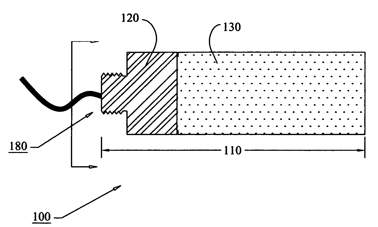
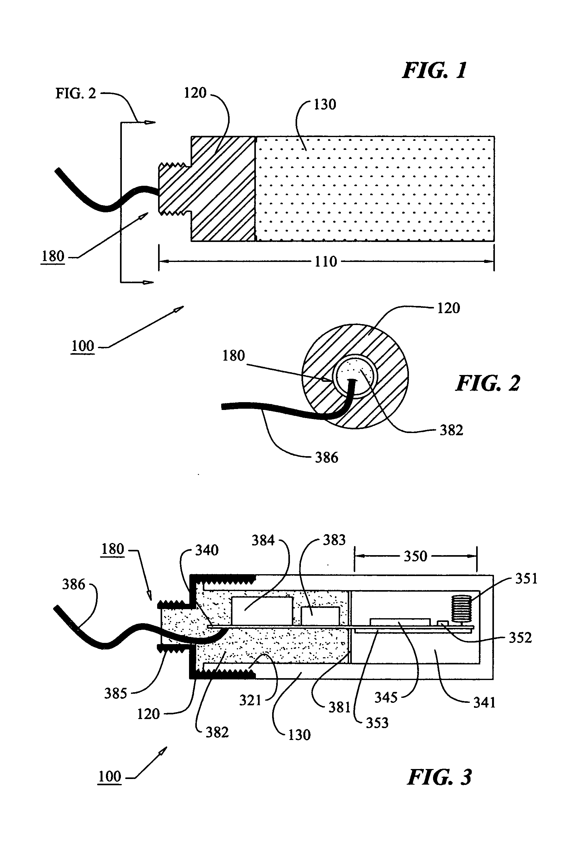
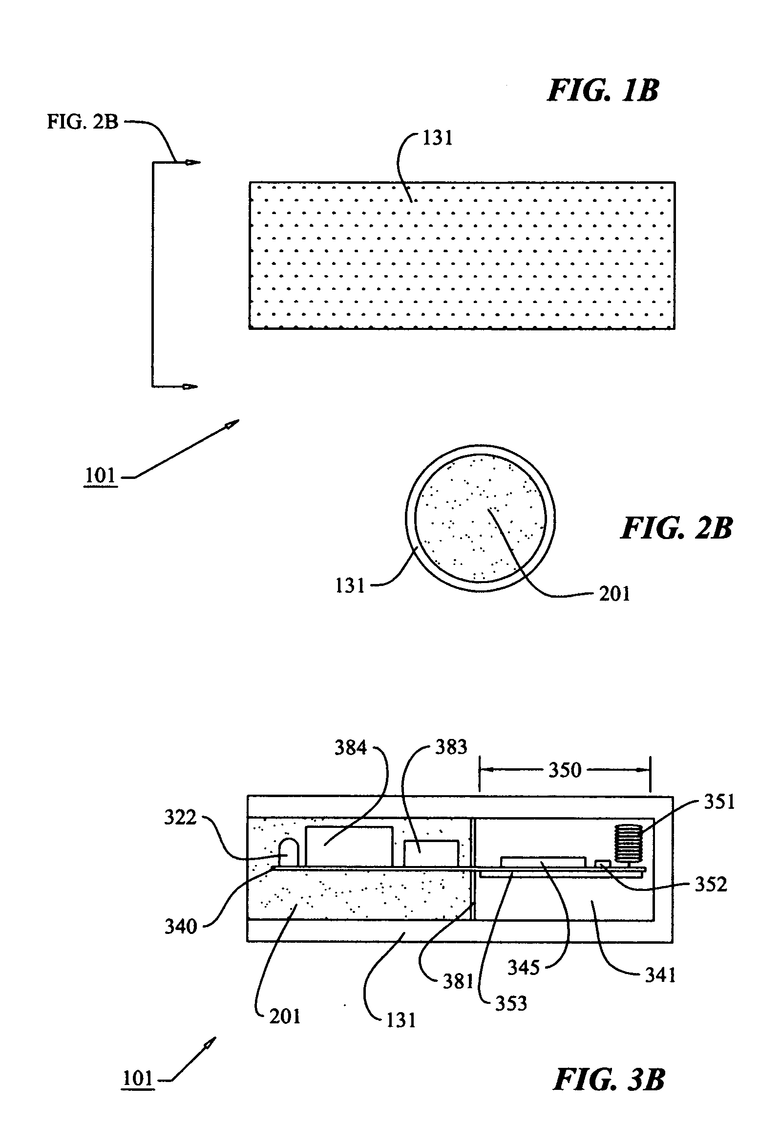
A self-contained radio frequency (RF) wireless communication device (100) comprising an explosion-proof housing (110), an internal electronic system for the conversion of radio wave and conducted electrical signals, and an internal antenna system located within a non-metallic portion (130) of the housing for collecting and emitting radio wave energy. The antenna system enables the wireless communication device (100) to safely collect and emit radio wave energy using one or more optimally configured antenna resonators (351), with each antenna resonator differing each other antenna resonator by at least one attribute in a group of attributes comprising: frequency response, field polarization, and wavelength spatial diversity.The present invention is a self-contained RF wireless communication device that provides data communications between two or more devices for the supervisory control and / or data acquisition of actuators, sensors, transducers, gas detectors, and other devices located in explosive hazardous locations without the need of installing one or more external antennas, one or more antenna connectors, excessive conduit connections and seals, and the like, whereby reducing system installation components count and eliminating conduit connections, furthermore reducing the probability of system-level failures caused by lower-level faults of components and conduit connections, resulting in a less expensive and safer electrical equipment installation.

Description

CROSS-REFERENCES TO RELATED APPLICATIONS AND INFORMATION DISCLOSURE[0001]This application claims benefit of U.S. Provisional Application Ser. No. 60 / 897,657 filed Jan. 26, 2007.6,900,565May, 2005Preston7,057,577June 2006Willoughby, et al.7,014,502March 2006Rasmussen6,978,165December 2005Martinez, et al.6,967,589November 2005Peters6,894,659May, 2005Pepperling, et al.6,794,991September 2004Dungan6,369,715April 2002Bennett, Jr., et al.OTHER REFERENCES AND DISCLOSURE INFORMATION[0002]1. Titan Industries, Inc. publication entitled “CK-485MX Wireless Transceiver”, document number DOC485MX, version 2.0, pages 2-6, author Dr. Brian Kopp, published Jun. 6, 1997 and downloaded from the www.titan-solutions.com on Dec. 26, 2006.[0003]2. Titan Industries, Inc. publication entitled “RTU System Radio Installation”, document number TI-INSTALL-1, rev 0, sheet 1 of 1, drawn by Lloyd, dated May 17, 1999 and downloaded from the website www.titan-solutions.com on Dec. 26, 2006.[0004]3. Honeywell Inc. pu...

Claims


Application Information

Patent Timeline
Patent Type & Authority Applications(United States)
IPC IPC(8): H04B1/38
CPCH01Q1/002H04B1/40H01Q21/30H01Q11/08
Inventor BOREN, WILLIAM BRET
Owner IP SENSING
Learn More