
Variable displacement pump

a variable displacement, pump technology, applied in the direction of machines/engines, positive displacement liquid engines, liquid fuel engines, etc., can solve the problems of excessive reduction of the diameter of the damper orifice, reducing the relief quantity, etc., and suppressing the increase of the pump chamber

Active Publication Date: 2009-03-26
HITACHI ASTEMO LTD
View PDF7 Cites 14 Cited by
  • Summary
  • Abstract
  • Description
  • Claims
  • Application Information

AI Technical Summary

Benefits of technology

The present invention provides a variable displacement pump that solves the problem of vibration and heating caused by the relief valve and the pressure regulating valve in the power steering apparatus of a vehicle. The invention achieves this by designing the orifice diameters of the pilot orifice and the damper orifice to optimize the flow rate of the pump and reduce the excessive increase of pump chamber pressure. The invention also includes a relief valve to discharge the excessive pressure in the pump chamber and a pilot orifice and a damper orifice to prevent the pulsation and vibration of the pressure regulating valve. The overall effect of the invention is to reduce the vibration and heating of the pump, improve energy conservation, and prevent excessive internal circulation.

Problems solved by technology

However, in a case in which the diameter of the pilot orifice is excessively decreased, the relief quantity is decreased, and the vibration tends to be caused by opening and closing repeat operations of the ball valve element of the relief valve.
However, in a case in which the diameter of the damper orifice is excessively decreased, the high pressure chamber on the downstream side of the damper orifice becomes the low pressure at the high discharge pressure of the pump.

Method used


Image

  • Variable displacement pump
  • Variable displacement pump
  • Variable displacement pump

Examples


Embodiment Construction

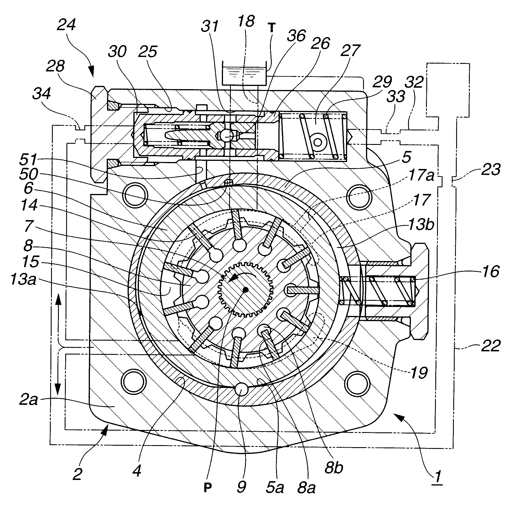
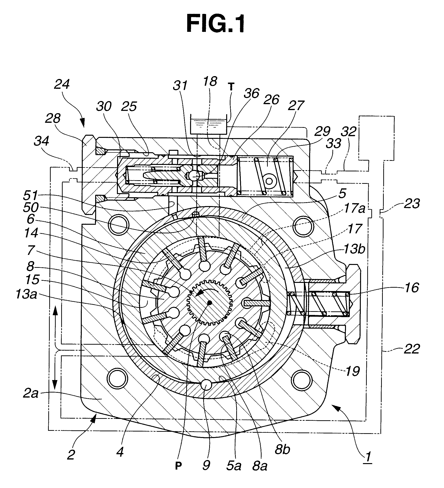
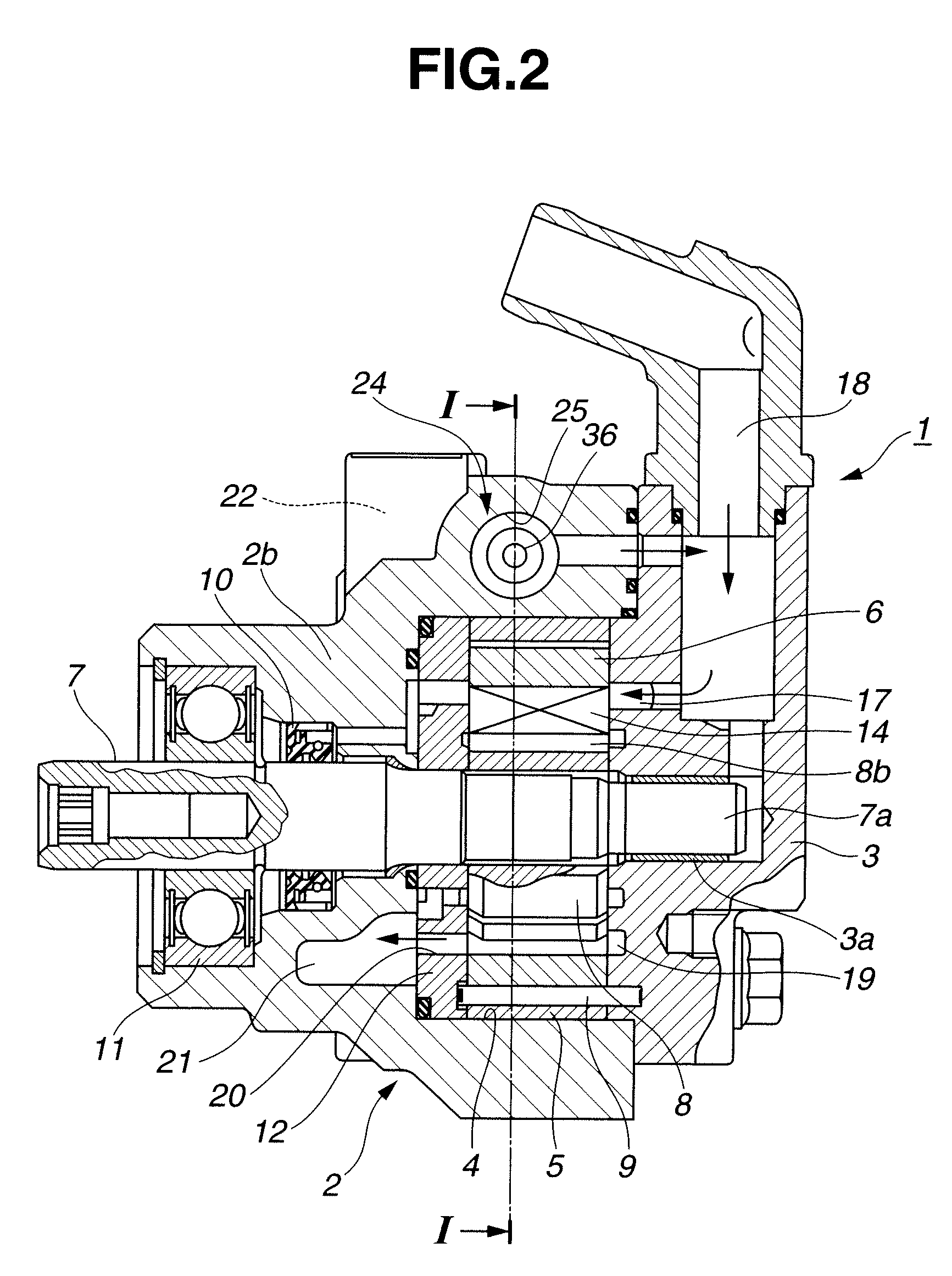
[0031]FIG. 1 is a sectional view which shows a variable displacement pump according to an embodiment of the present invention, and which is taken along a section line I-I of FIG. 2. FIG. 2 is a longitudinal sectional view showing the variable displacement pump of FIG. 1. FIG. 3 is a front view showing a front body of the variable displacement pump of FIG. 1. FIG. 4 is a sectional view taken along a section line IV-IV of FIG. 3. FIG. 5 is a sectional view taken along a section line V-V of FIG. 3. This variable displacement pump of FIG. 1 includes a pump body 1 having a front body 2 and a rear body 3 serving as a first plate member; an adapter ring 5 mounted and fixed in a receiving space 4 formed in pump body 1; a cam ring 6 arranged to swing in left and right directions of FIG. 1 within a substantially oval space of adapter ring 5; a driving shaft 7 inserted into and rotatably supported by pump body 1; and a rotor 8 rotatably disposed radially inside cam ring 6, and connected with d...


PUM


Abstract

A variable displacement pump includes: a pump body; a rotor; a cam ring; inlet and outlet ports; first and second fluid pressure chambers; a metering orifice provided in a discharge passage connected with the outlet port; a pressure regulating section arranged to regulate the pressure introduced into the first or second fluid pressure chamber, and including a high pressure chamber, a middle pressure chamber, and a low pressure chamber; a relief valve; a pilot orifice provided in a passage connecting the metering orifice and the middle pressure chamber, and having a circular section with a diameter of a mm; and a damper orifice provided in a passage connecting the outlet port and the high pressure chamber, and having a circular section with a diameter of b mm. The pilot orifice and the damper orifice satisfy the following relationships: a+2b−2.1≧0, −4a+b−16.3≦0, and a≦1.8.

Description

BACKGROUND OF THE INVENTION[0001]This invention relates to a variable displacement pump used as a hydraulic source and so on of a power steering apparatus of a vehicle.[0002]U.S. Pat. No. 6,524,076 B2 (corresponding to Japanese Patent Application Publication No. 2001-304139) shows a variable displacement pump for a power steering apparatus of a vehicle. This variable displacement pump includes an adapter ring disposed in a pump body; a cam ring disposed radially inside the adapter ring, and arranged to swing about a support shaft disposed in an axial direction at a lower portion of an inner circumference surface of the adapter ring; a drive shaft rotatably supported through forward and rearward bearing bushes in the pump body; and a rotor connected with the drive shaft by a serration portion located at a substantially central portion of the drive shaft in the axial direction, and arranged to rotate within the cam ring.[0003]In an outer circumference portion of the rotor, there are p...

Claims


Application Information

Patent Timeline
Patent Type & Authority Applications(United States)
IPC IPC(8): F04B49/00F04B49/22
CPCF04C2/3442F04C14/10F04C14/24F04C14/226F04C2220/24F04C2250/10F04C15/0049
Inventor SOEDA, JUNUCHIDA, YUKIO
Owner HITACHI ASTEMO LTD
Learn More