
Intrusion Detection Sensor

a detection sensor and intrusion detection technology, applied in the field of intrusion detection sensors, can solve the problems of sensor generating false alarm, etc., and achieve the effect of improving operational reliability and improving operational reliability

Inactive Publication Date: 2009-03-26
OPTEX CO LTD
View PDF12 Cites 22 Cited by
  • Summary
  • Abstract
  • Description
  • Claims
  • Application Information

AI Technical Summary

Benefits of technology

[0032]According to the intrusion detection sensor of the present invention, it is possible to suppress the influence of rain, insects, or the like coming close to the sensor, the installation location, vibration of the intrusion detection sensor itself, or the like, and to avoid false alarms and the like to the highest degree possible, and therefore the operational reliability can be improved. Furthermore, by prohibiting detection in a predetermined direction or by changing the detection sensitivity according to the directions, it is possible to further improve the operational reliability.

Problems solved by technology

However, problems such as the following arise when using this type of sensor as a crime prevention sensor and recognizing a change in the phase difference over time in order to recognize only the detection target object moving in the detection area.
For example, when this type of sensor is installed outdoors, the sensor may generate a false alarm by erroneously detecting a tree, a bush, or the like swaying in the wind as a detection target object.
Similarly, when this type of sensor is installed indoors, the sensor may generate a false alarm by erroneously detecting, as a detection target object, an object other than a human body (a non-detection target object), such as rotational movement of a ventilation fan, blinds or curtains swaying in the wind, or even vibration of the microwave sensor itself.

Method used


Image

  • Intrusion Detection Sensor
  • Intrusion Detection Sensor
  • Intrusion Detection Sensor

Examples


embodiment 1

Variation of Embodiment 1

[0104]FIG. 4 is a block diagram illustrating an overall configuration of an intrusion detection sensor 100A in which the operational reliability is further improved by incorporating a passive type infrared sensor (PIR sensor), as a variation of the intrusion detection sensor 100 according to Embodiment 1. Hereinafter, only differences from Embodiment 1 shall be described.

[0105]As shown in FIG. 4, this intrusion detection sensor 100A includes, in addition to the components of Embodiment 1, a passive type infrared sensor 140 that receives infrared rays from the detection area, and outputs a signal that indicates the presence or absence of a detection target object based on a temperature difference from the surroundings (a high level if a detection target object is present, and a low level if no detection target object is present).

[0106]Another difference is that in a one-chip microcomputer 130A, the output from the passive type infrared sensor 140 is connected...

embodiment 2

[0109]FIG. 5 is a block diagram illustrating an overall configuration of an intrusion detection sensor 200 according to Embodiment 2 of the present invention. Because Embodiment 2 is identical to the variation of Embodiment 1 except for the following differences, the same reference numerals are given to the same components, and the descriptions shall focus primarily on the differences.

[0110]As shown in FIG. 5, a difference between this intrusion detection sensor 200 and the intrusion detection sensor 100A lies in the components of a one-chip microcomputer 230. More specifically, a detection target object direction identification unit 234 and a detection prohibition direction storage unit 235 are added, and the outputs of the detection target object direction identification unit 234 and the detection prohibition direction storage unit 235 are also taken into consideration for the control of the output of the alarm signal Dout2 by the alarm output control unit 233. Also, the output of...

embodiment 3

[0115]FIG. 6 is a block diagram illustrating an overall configuration of an intrusion detection sensor 300 according to Embodiment 3 of the present invention. The same reference numerals are given to the same components as those of the above-described embodiments, and the descriptions shall focus primarily on the differences.

[0116]As shown in FIG. 6, this intrusion detection sensor 300 includes: a phased array antenna 310 that can change the transmission / reception direction of microwaves; a microwave sensor 320 that performs detection of a detection target object such as a human body using this phased array antenna 310; a passive type infrared sensor 140; and a one-chip microcomputer 330 that controls the phased array antenna 310, the microwave sensor 320, and the passive type infrared sensor 140.

[0117]The phased array antenna 310 has a plurality of antenna elements 311 that are arranged at an equal spacing toward the same direction, and a phase shift control circuit 312 that contro...


PUM


Abstract

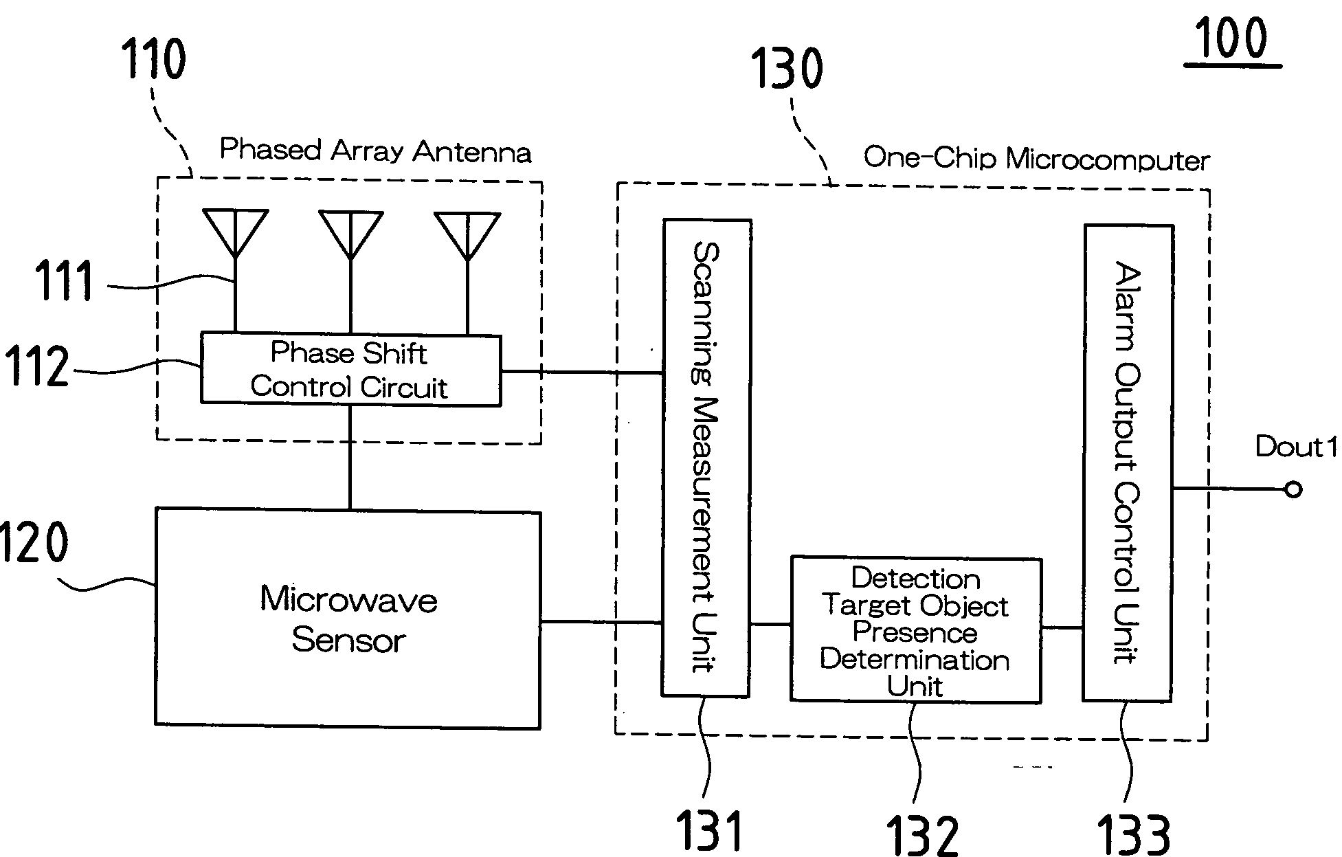
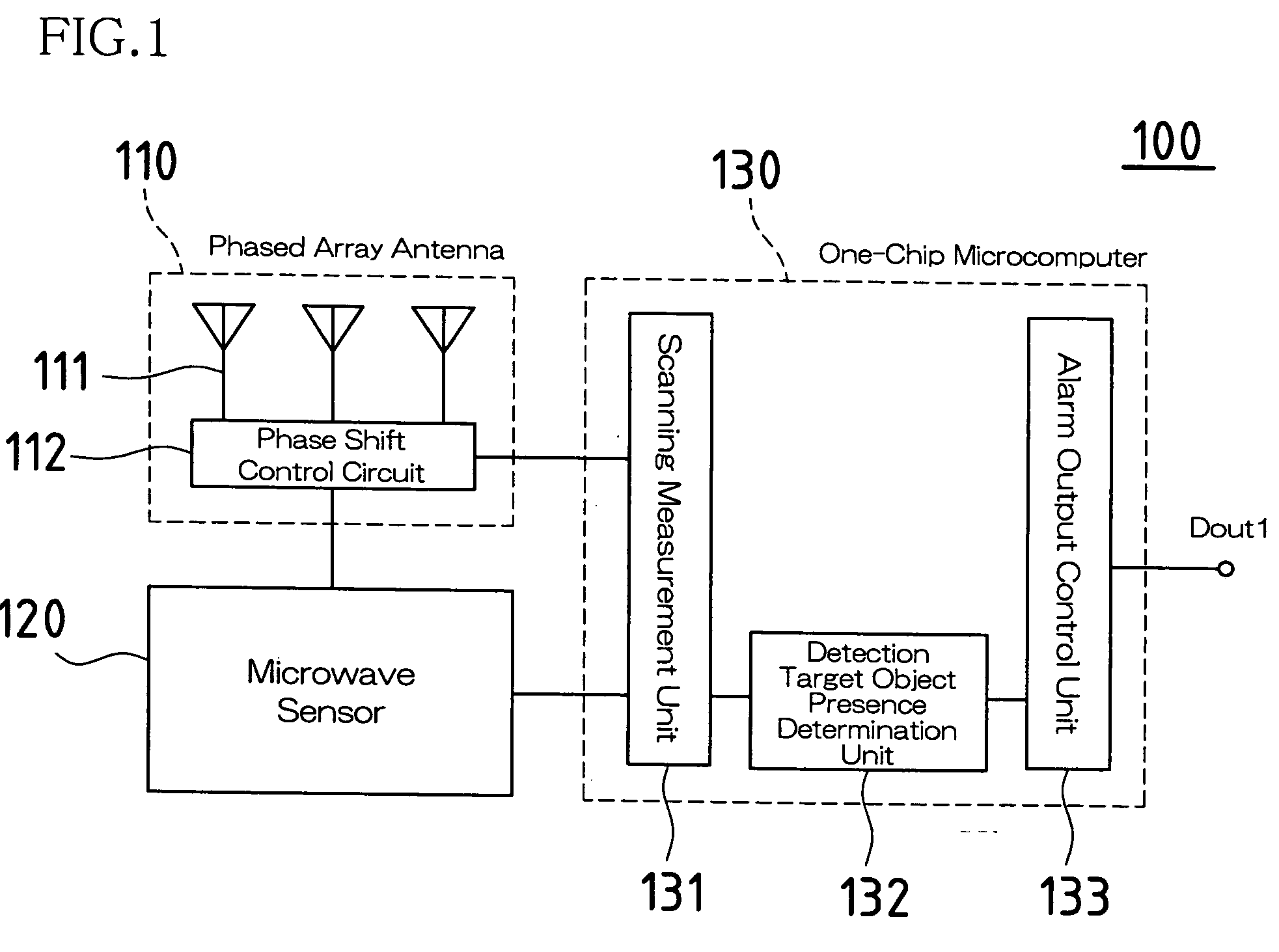
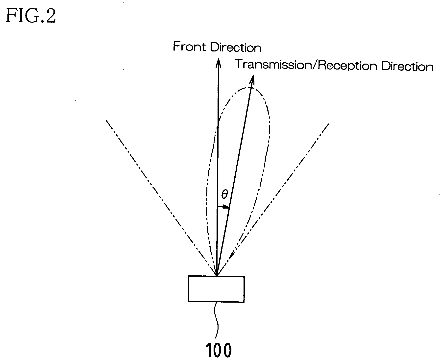
According to an embodiment, an intrusion detection sensor includes a microwave sensor (120) that transmits microwaves toward a detection area, receives the microwaves reflected by an object present in the detection area, and outputs a reflected wave reception intensity signal according to the received intensity; a direction variable antenna device (110); a scanning measurement means (131) that provides an instruction to scan the transmission / reception direction to the direction variable antenna device (110) to determine a relationship with the output of the reflected wave reception intensity signal; a detection target object presence determination means (132) that determines whether or not a detection target object is present based on the determined relationship; and an alarm signal output control means (133) that outputs an alarm signal when it is determined that a detection target object is present.

Description

TECHNICAL FIELD[0001]The present invention relates to an intrusion detection sensor having a built-in microwave sensor, and particularly to an intrusion detection sensor that improves reliability by avoiding the occurrence of false alarms to the highest degree possible.BACKGROUND ART[0002]A microwave sensor that detects a human body (intruder) by transmitting microwaves toward a detection area and receiving waves reflected off of the human body (microwaves modulated by the Doppler Effect) is known as an example of a conventional crime prevention device (for example, see Patent Document 1).[0003]Furthermore, one type of microwave sensor that has been proposed involves measuring the distance to the detection target object, such as a human body, present in the detection area by using a plurality of types of microwaves of different frequencies. This type of sensor is configured such that, for example, two types of microwaves of different frequencies are transmitted toward the detection ...

Claims


Application Information

Patent Timeline
IPC IPC(8): G08B13/18
CPCG01S13/04G01S13/06G08B13/2494G01V8/005G08B13/187G01S13/886
Inventor TSUJI, MASATOSHI
Owner OPTEX CO LTD
Learn More