Surgical stapler with magnetically secured components
- Summary
- Abstract
- Description
- Claims
- Application Information
AI Technical Summary
Benefits of technology
Problems solved by technology
Method used
Image
Examples
Embodiment Construction
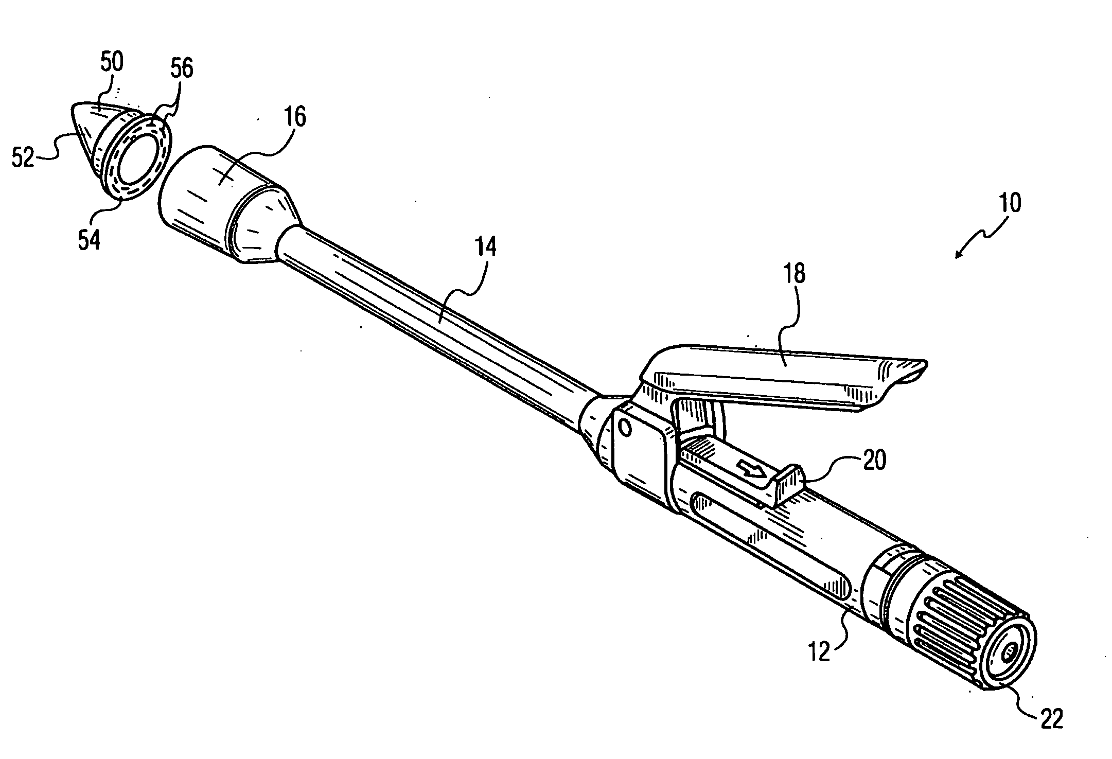
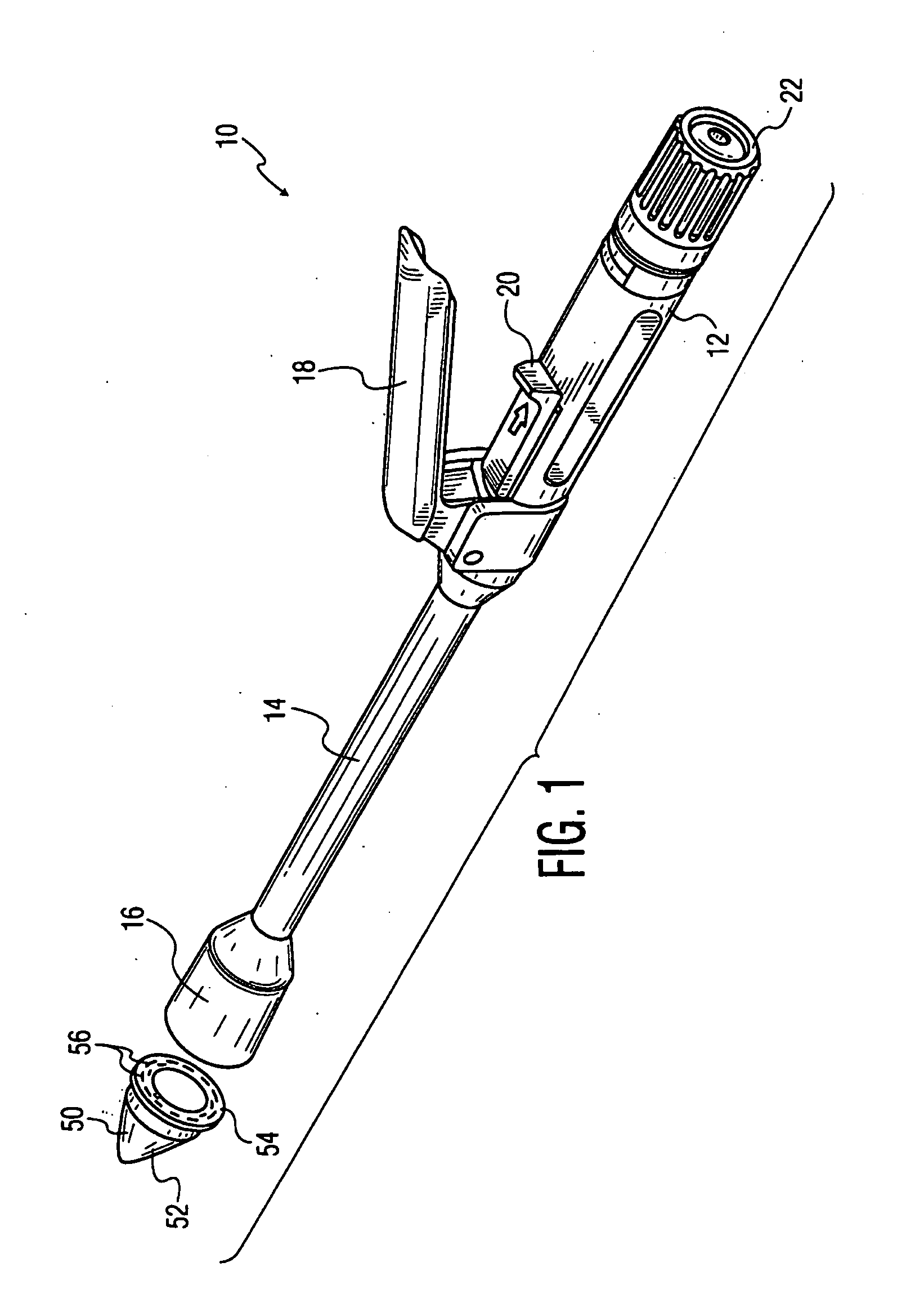
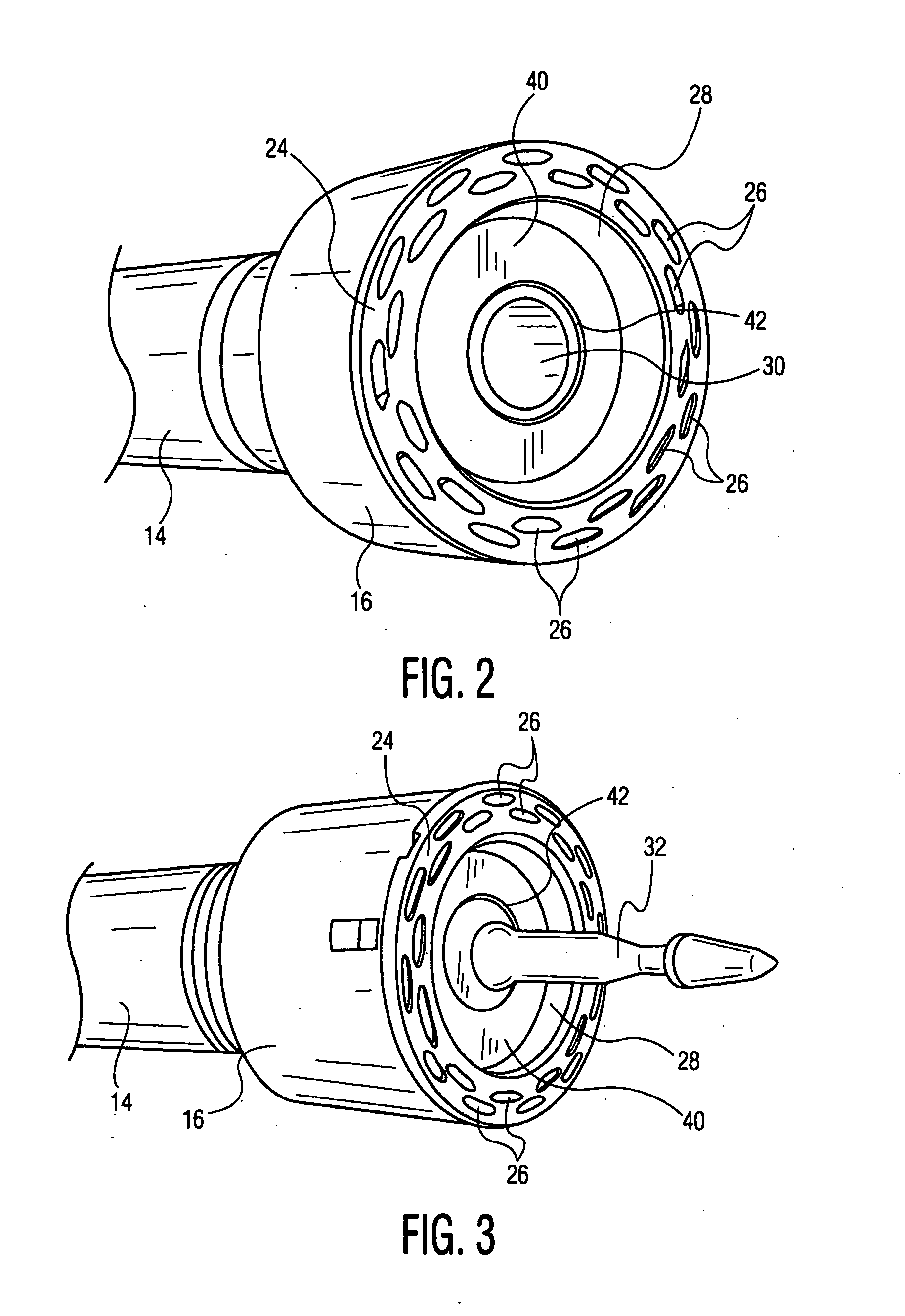
[0029]FIG. 1 schematically represents a preferred embodiment of an EEA stapler 10 in accordance with an embodiment of the present invention. As is conventional, the stapler 10 includes a stapler body with a handle 12, an elongated shaft 14, and a head 16 at a distal end of the shaft 14. The handle includes a trigger 18 and a safety 20 that prevents inadvertent actuation of the trigger. When the safety is in an “Off” position, the trigger 18 can be actuated to forcibly eject staple blanks from a staple cartridge in the head 16. A thumb screw 22 provides for manual operation of certain staple components, as discussed in more detail below. The general configuration of the stapler 10, and the internal mechanisms for ejecting staples from the head 16, is conventional. The construction of these parts is familiar to those skilled in the art, and accordingly, they are not described herein in further detail. Those construction details can be, for example, as shown in any of the patents menti...
PUM
| Property | Measurement | Unit |
|---|---|---|
| Permeability | aaaaa | aaaaa |
| Magnetism | aaaaa | aaaaa |
Abstract
Description
Claims
Application Information
 - R&D Engineer
- R&D Manager
- IP Professional
- Industry Leading Data Capabilities
- Powerful AI technology
- Patent DNA Extraction
Browse by: Latest US Patents, China's latest patents, Technical Efficacy Thesaurus, Application Domain, Technology Topic, Popular Technical Reports.
© 2024 PatSnap. All rights reserved.Legal|Privacy policy|Modern Slavery Act Transparency Statement|Sitemap|About US| Contact US: help@patsnap.com


