
Simulation dog tail swinging installment

a technology of swinging installment and dog tail, which is applied in the field of toys, can solve the problems of high manufacturing cost of existing swinging installment, short life of batteries for powering the swinging installment, and the inability to vividly swing the tail when simulating the swinging installment, etc., and achieve the effect of manufacturing with a lower cos

Inactive Publication Date: 2011-01-06
TSUI KING LAM
View PDF2 Cites 368 Cited by
  • Summary
  • Abstract
  • Description
  • Claims
  • Application Information

AI Technical Summary

Benefits of technology

[0004]Accordingly, the present invention is directed to a toy tail swinging installment which can be manufacture with lower cost.
[0006]The present invention is further directed to a toy tail swinging installment which is more energy-saving.
[0012]In another aspect, the present invention provides a simulation tail swinging installment for swinging a simulation tail comprising a plurality of articulated members. The swinging installment includes a battery module, electromagnetic coils disposed at opposite sides of the articulated members, and an iron members disposed at joints of the articulated members. The simulation tail swinging installment further includes a control circuit configured to control the battery module to selectively supply power to electromagnetic coils at only one of the opposite sides of the articulated members at a time thus causing a swinging activity of the simulation tail.
[0025]The pulley may be used to guide the first driving cable as well as reduce friction between the first driving cable and various parts of the swinging installment thus protecting the driving cable.
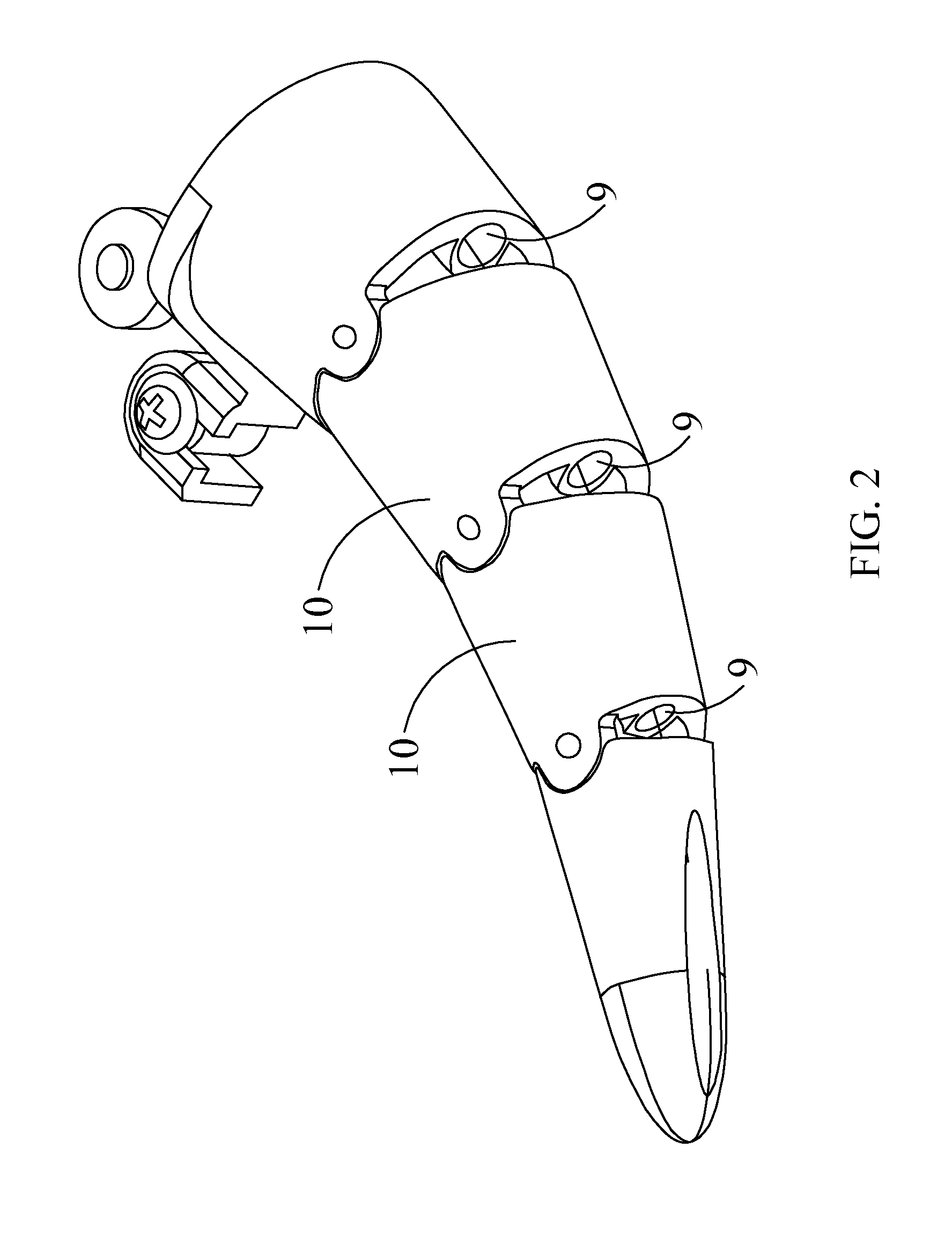
[0026]The cable holes formed in the articulated members of the simulation tail can also guide and protect the driving cables.
[0027]In view of the foregoing, the present simulation tail swinging installment operates based on the electromagnetic driving principle, such that the simulation animal tail can be driven to swing vividly by consuming lower energy. Therefore, the present simulation tail swinging installment can have al lower manufacturing cost, produce less noise as well as consume less energy thus prolonging the use time of the battery module.

Problems solved by technology

However, the swinging installment of the existing animal toys can not vividly swing the tail when simulating the tail swing.
In addition, the manufacturing cost of the existing swinging installment is high.
Moreover, the existing swinging installment consumes is too energy-consuming which results in a short life of batteries for powering the swinging installment.

Method used


Image

  • Simulation dog tail swinging installment
  • Simulation dog tail swinging installment
  • Simulation dog tail swinging installment

Examples


first embodiment

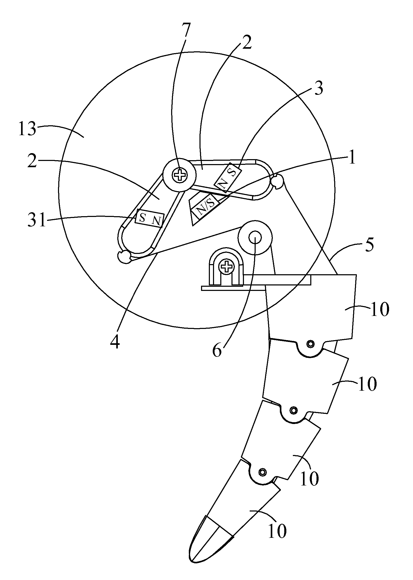
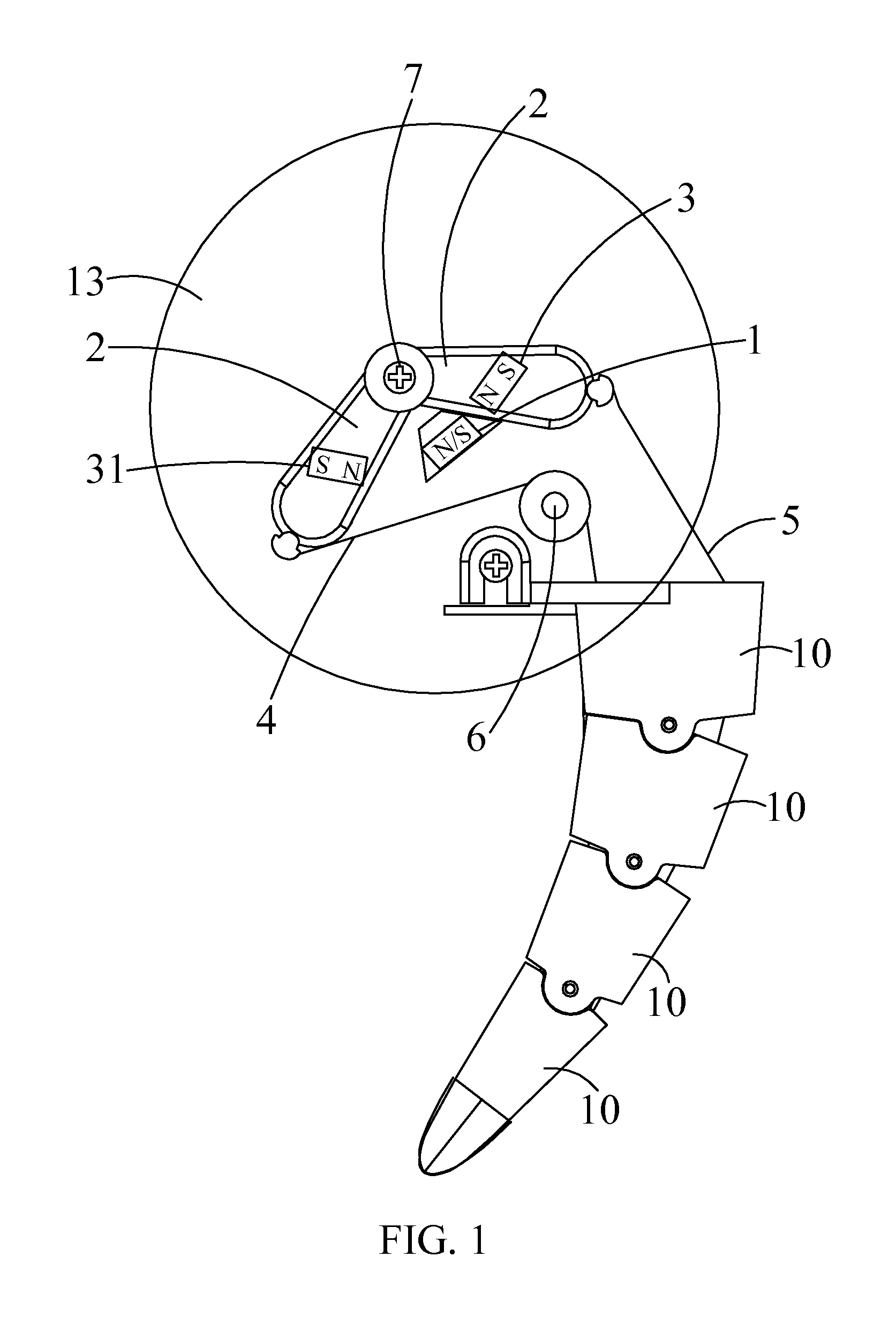
[0036]Referring to FIGS. 1, 2 and 5, a simulation tail swinging installment or apparatus in accordance with a first embodiment is illustrated for swinging a simulation dog tail 10. As shown, the simulation dog tail 10 includes a plurality of articulated members which provide the free swinging activity of the simulation tail through relative movements between the articulated members. The simulation dog tail 10 is illustrated as having four articulated members. It should be understood, however, that the number of the articulated members of the simulation dog tail 10 can be varied based on actual requirements or designs. While the simulation tail swinging installment is described herein in conjunction with the simulation dog tail 10, it is noted that the simulation tail swinging installment described herein can also be used with another animal's tail such as a cat tail.

[0037]The simulation tail swinging installment includes a base plate 13, an electromagnetic coil 1 mounted on the base...

second embodiment

[0046]Referring to FIGS. 3, 4 and 5, a simulation tail swinging installment or apparatus in accordance with a second embodiment is illustrated for swinging a simulation dog tail. As shown, the simulation dog tail includes a plurality of articulated members which provide the free swinging activity of the simulation tail through relative movements between the articulated members. The simulation dog tail is illustrated as having four articulated members. It should be understood, however, that the number of the articulated members of the simulation dog tail can be varied based on actual requirements or designs. While the simulation tail swinging installment is described herein in conjunction with the simulation dog tail, it is noted that the simulation tail swinging installment described herein can also be used with other animal's tail such as a cat tail.

[0047]The simulation tail swinging installment of the second embodiment includes a plurality of electromagnetic coils 101 and a solar ...


PUM


Abstract

A simulation tail swinging installment includes a base plate, an electromagnetic coil disposed on the base plate, a battery module configured for supplying power to the electromagnetic coil, and a control circuit coupled to the battery module. The simulation tail swinging installment further includes a furcated component having two arms disposed with respect to the electromagnetic coil, with the two arms located on opposite sides of the electromagnetic coil, respectively. Each of the arms includes a permanent magnet positioned in correspondence with the electromagnetic coil. The furcated component is mounted to the base plate through a pivot connected to the base plate. A first driving cable and a second driving cable are attached to the two arms, respectively. The first driving cable and the second driving cable extend through and along two side portions of a simulation tail and secured to a distal end of the simulation tail.

Description

BACKGROUND OF THE INVENTION[0001]The present invention relates generally to toys, and more particularly, to a tail swinging installment for use in an animal toy.[0002]Various toys that simulate the shape of animals are currently being developed. With continuous advancing of the manufacturing process and in order to meet the consumer's needs, this type of toys look increasingly life-like, which brings people joy. Some live animals such as dogs swing their tails to send a message of friendliness when approaching their masters. Some of current animal toys also have a similar simulation tail swinging installment. However, the swinging installment of the existing animal toys can not vividly swing the tail when simulating the tail swing. In addition, the manufacturing cost of the existing swinging installment is high. Moreover, the existing swinging installment consumes is too energy-consuming which results in a short life of batteries for powering the swinging installment.[0003]What is n...

Claims


Application Information

Patent Timeline
Patent Type & Authority Applications(United States)
IPC IPC(8): A63H3/20
CPCA63H3/48A63H3/20
Inventor LAM, TSUI KING
Owner TSUI KING LAM
Learn More