Eureka AIR delivers breakthrough ideas for toughest innovation challenges, trusted by R&D personnel around the world.

Optical scanning device and image forming apparatus including same

a scanning device and image forming technology, applied in the direction of electrographic process apparatus, instruments, corona discharge, etc., can solve the problems of color shift, uneven image density, image deterioration, etc., to prevent image deterioration and suppress vibration transmission

Inactive Publication Date: 2009-03-19
RICOH KK
View PDF6 Cites 14 Cited by
  • Summary
  • Abstract
  • Description
  • Claims
  • Application Information

AI Technical Summary

Benefits of technology

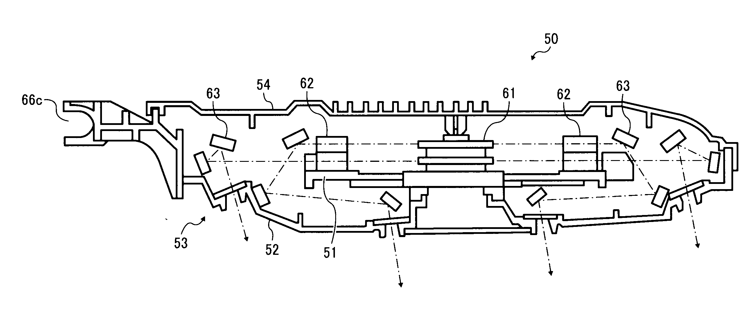
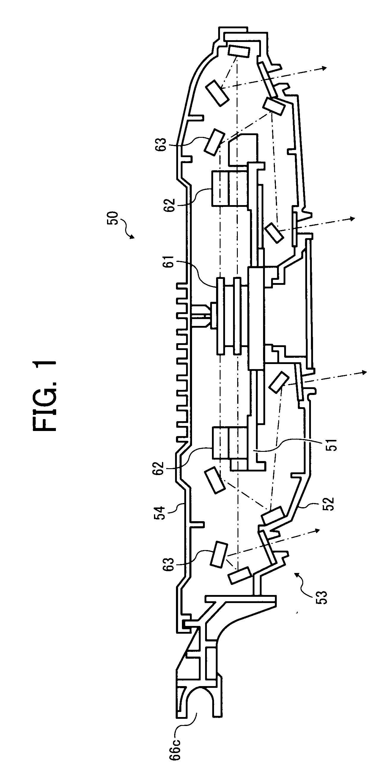
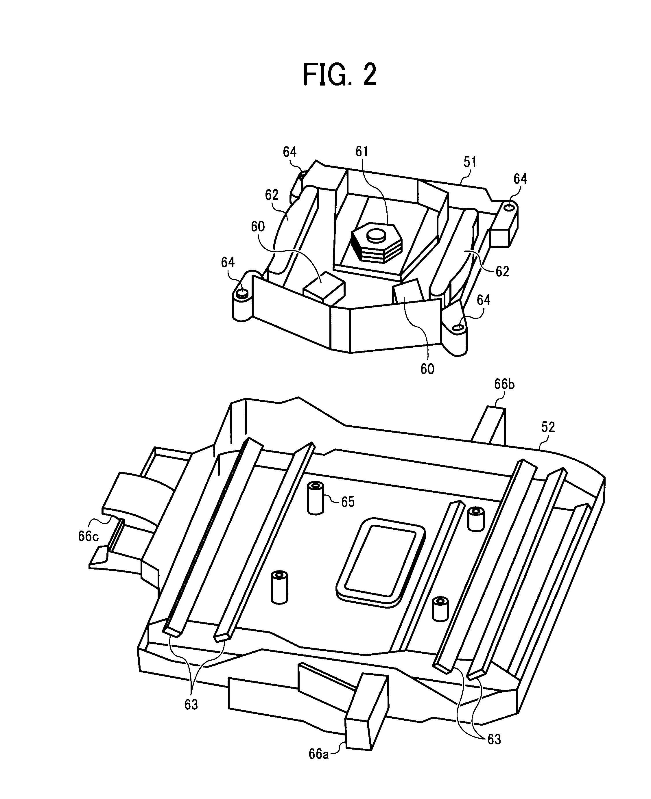
The present invention provides an optical scanning device and an image forming apparatus that can prevent image deterioration and provide high-quality images. The optical scanning device includes multiple optical housings that suppress transmission of vibration from one optical housing to another, and an image forming apparatus includes the optical scanning device. The optical scanning device includes a first housing with a rotating deflector, a second housing with one or more reflecting mirrors, and three supporting members that support the second housing relative to the image forming apparatus. The first housing is mounted inside the second housing, and mounts to fix the first housing to the second housing are positioned substantially on or within sides of a triangle formed by the three supporting members. The image forming apparatus includes a latent image bearing member, a charging device, an irradiating device, a developing device, a transfer device, and a fixing device. The irradiating device includes the optical scanning device described above.

Problems solved by technology

However, the above-described optical scanning device using the rotating deflector is susceptible to vibration due to high-speed rotation of a polygon mirror, possibly resulting in image deterioration such as color shift and uneven image density.
However, the image forming system disclosed in JP-A-2006-323066 requires higher cost to include the vibration unit and multiple detectors.
Further, although a method for suppressing transmission of the vibration by improving rigidity of the optical scanning device is disclosed in JP-A-2002-341467, the range of available layouts of the optical scanning device is more limited because the optical scanning device needs to be fixed to a main frame of an image forming apparatus.
However, as described above, in the optical scanning device using the rotating deflector, the polygon mirror is rotated at high speed and vibration is transmitted from the optical housing including the rotating deflector to the other optical housing.
Consequently, portions of the other optical housing cantilevered to the image forming apparatus are heavily susceptible to vibration, resulting in image deterioration.

Method used


Image

  • Optical scanning device and image forming apparatus including same
  • Optical scanning device and image forming apparatus including same
  • Optical scanning device and image forming apparatus including same

Examples


Embodiment Construction

[0030]In describing exemplary embodiments illustrated in the drawings, specific terminology is employed for the sake of clarity. However, the disclosure of this patent specification is not intended to be limited to the specific terminology so selected, and it is to be understood that each specific element includes all technical equivalents that operate in a similar manner and achieve a similar result.

[0031]Exemplary embodiments of the present invention are now described below with reference to the accompanying drawings.

[0032]In a later-described comparative example, exemplary embodiment, and exemplary variation, for the sake of simplicity the same reference numerals will be given to identical constituent elements such as parts and materials having the same functions, and redundant descriptions thereof omitted unless otherwise stated.

[0033]Typically, but not necessarily, paper is the medium from which is made a sheet on which an image is to be formed. It should be noted, however, tha...


PUM


Abstract

An optical scanning device including a first housing including a rotating deflector configured to deflect a light beam from at least one light source to scan a surface to be scanned with a deflected light beam, a second housing including one or more reflecting mirrors, and three supporting members configured to support the second housing relative to an image forming apparatus. The first housing is mounted inside the second housing, and mounts to fix the first housing to the second housing are positioned substantially on or within sides of a triangle formed by the three supporting members.

Description

CROSS-REFERENCE TO RELATED APPLICATIONS[0001]The present patent application is based on and claims priority pursuant to 35 U.S.C. §119 from Japanese Patent Application No. 2007-239714, filed on Sep. 14, 2007 in the Japan Patent Office, the entire contents of which are incorporated herein by reference.BACKGROUND OF THE INVENTION[0002]1. Field of the Invention[0003]Exemplary aspects of the present invention generally relate to an optical scanning device employed in a writing system in an image forming apparatus such as a digital copier and a laser printer, and an image forming apparatus including the optical scanning device.[0004]2. Description of the Background[0005]Related-art image forming apparatuses, such as a copier, a facsimile machine, a printer, or a multifunction printer having two or more of copying, printing, scanning, and facsimile functions, form a toner image on a recording medium (e.g., a sheet) according to image data using an electrophotographic method. In such a met...

Claims


Application Information

Patent Timeline
Patent Type & Authority Applications(United States)
IPC IPC(8): G03G15/02
CPCB41J2/473
Inventor YAMAZAKI, KOZO
Owner RICOH KK
Why Eureka
Eureka Blog
Learn More