
Adaptive array control device, method and program, and adaptive array processing device, method and program

a control device and array technology, applied in the direction of multi-channel direction-finding systems using radio waves, instruments, systems with undesired wave elimination, etc., can solve the problems of unfavorable detection of interference, and deterioration of the quality of the adaptive array device output which is the final output, etc., to achieve high-quality identification information

Inactive Publication Date: 2009-03-19
NEC CORP
View PDF2 Cites 14 Cited by
  • Summary
  • Abstract
  • Description
  • Claims
  • Application Information

AI Technical Summary

Benefits of technology

[0049]With the configuration described above, in the present invention, as identification information of a target signal and interference by amplitude is corrected according to identification information of the target signal and the interference by phases, it is possible to acquire highly accurate identification information of the target signal and the disturbing in which the identification information by amplitude and the identification information by phase are combined. As such, coefficient updating control of the adaptive array processing device can be performed appropriately, whereby high-quality array processing outputs which are less influenced by the frequency characteristics and incoming directions of input signals can be acquired.

Problems solved by technology

As such, in either case, the adaptive filter coefficient is disturbed, so that uncomfortable breathing noises are caused in the output signal of the array processing device.
However, a small step size causes a delay of the speed with which the characteristics of the adaptive blocking matrix circuit follows the movement of the target signal, so that the quality of the adaptive array device output which is the final output is deteriorated.
In an application of using normal audio signals, as the audio power may sometimes also be present outside this frequency range, presence of interferences cannot be detected accurately.
Further, as it is configured to control coefficient update of only multi-input canceller while assuming a fixed blocking matrix circuit, it cannot be directly applied to the adaptive blocking matrix circuit.
In this method, the adaptive blocking matrix circuit does not exhibit sufficient performance until the adaptive filter coefficient included in the adaptive blocking matrix circuit is converged, so that estimation of the interference power becomes inaccurate.
As such, particularly in the initial timing of operation, errors may be easily caused in the coefficient update control of the adaptive blocking matrix circuit and the multi-input canceller, leading to deterioration in the output audio of the array processing device.
As a result, the output of the multi-input canceller 500, that is, the output of the entire adaptive array device, is disturbed, causing uncomfortable breathing noises.
With the disturbing, the adaptive filter coefficient included in the multi-input canceller 500 is disordered, causing uncomfortable breathing noises in the adaptive array device output.

Method used


Image

  • Adaptive array control device, method and program, and adaptive array processing device, method and program
  • Adaptive array control device, method and program, and adaptive array processing device, method and program
  • Adaptive array control device, method and program, and adaptive array processing device, method and program

Examples


first exemplary embodiment

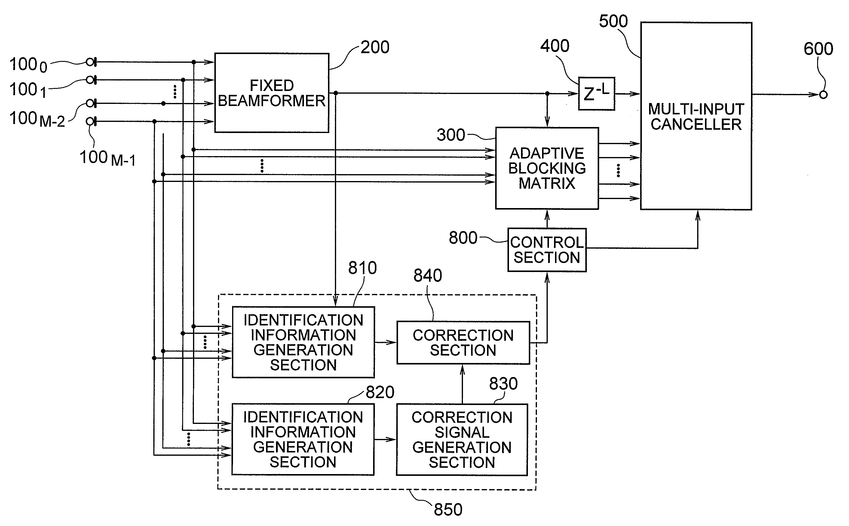
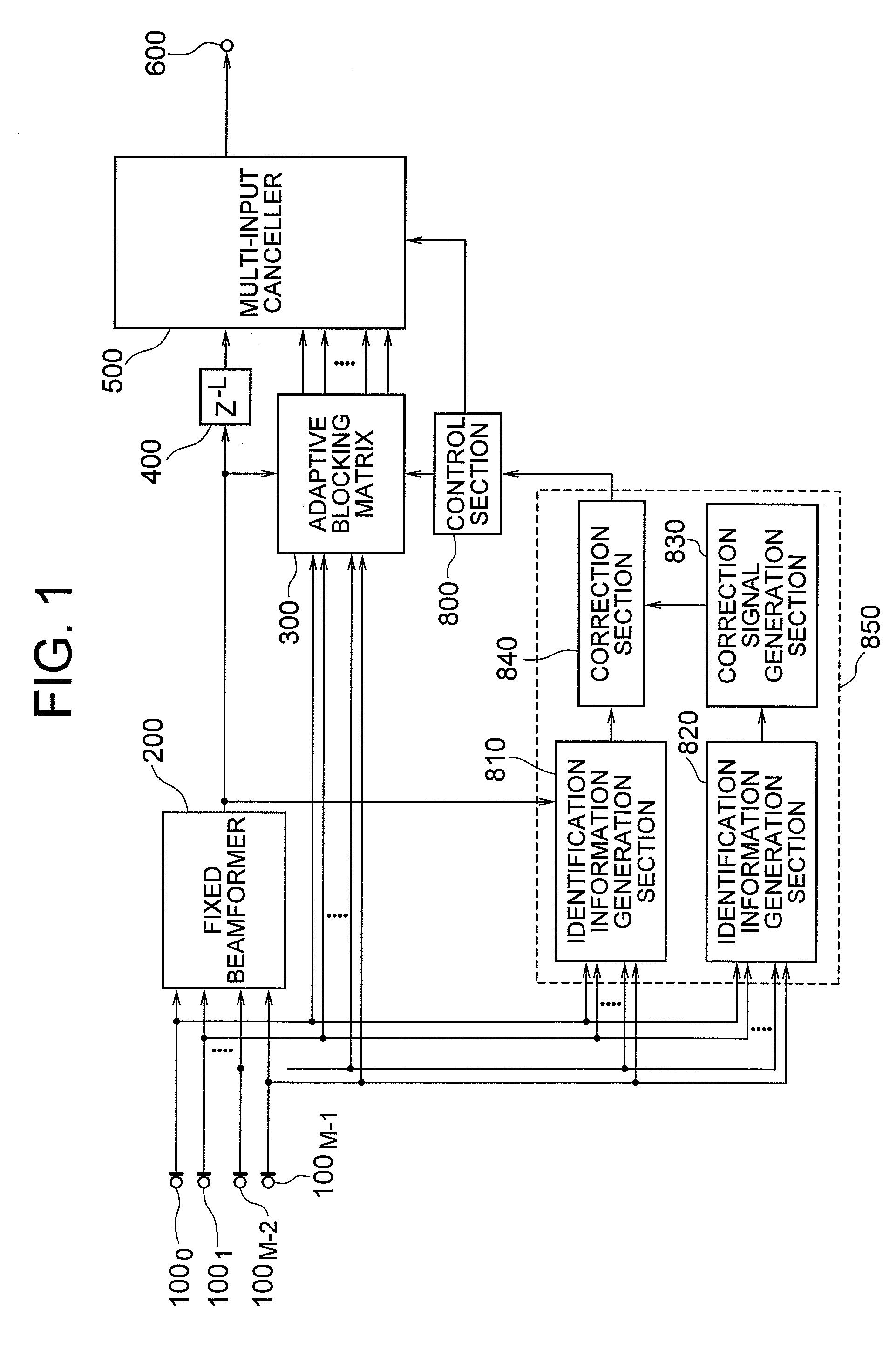
[0051]FIG. 1 is a block diagram showing an adaptive array device having an adaptive array control device according to a first exemplary embodiment of the invention. The first exemplary embodiment includes, in the conventional adaptive array control device shown in FIG. 31, in addition to an identification information generation section configured of a blocking matrix circuit 310 and an SIR calculation section 700, an identification information generation section 820, a correction signal generation section 830, and a correction section 840 are included. The identification information generation section 850 configured of the identification information generation section 810, the identification information generation section 820, the correction signal generation section 830, and the correction section 840 provide the same function as that of the conventional identification information generation section 810. Hereinafter, configuration and effects will be described mainly based on the o...

second exemplary embodiment

[0117]FIG. 30 is a block diagram showing an adaptive array device having an adaptive array control device according to a fourth exemplary embodiment of the invention. The second exemplary embodiment of the invention includes a computer (CPU; processor; data processing device) 1000 which operates in accordance with a program control, input terminals 1010 to 101M−1, and an output terminal 600. The computer (CPU; processor; data processing device) 1000 includes the fixed beamformer 200, the adaptive blocking matrix circuit 300, the delay element 400, the multi-input canceller 500, the identification information generation sections 810 and 820, the correction signal generation section 830, the correction section 840, and the controller 800.

[0118]Target signals and interferences supplied to the input terminals 1010 to 101M−1 are supplied to the array processing device in the computer 1000 where the interferences are suppressed. The main components of the array processing device are the f...


PUM


Abstract

[Object] By enabling accurate coefficient update, a high-quality array processing output which is less influenced by frequency characteristics and incoming directions of input signals control can be acquired, irrespective of the frequency characteristics and incoming direction of the input signals. [Achieving Means] Identification information of a target signal and interference by amplitude is corrected according to identification information of the target signal and the interference by phase, and with use of the correction result, identification of the target signal and the interference is performed. More specifically, an identification information generation section according to phase, a correction signal generation section, and a correction section are provided.

Description

TECHNICAL FIELD[0001]The present invention relates to an adaptive array control device, a method and their program, and an adaptive array processing device, a method, and their program. In particular, the present invention relates to an adaptive array control device, method and program for receiving signals with directivity using a plurality of sensors, and an adaptive array processing device, method, and its program.[0002]In the field of audio signal acquisition, sonars, and wireless communications, a speech enhancement device by means of an adaptive microphone array and a wireless transceiver by means of an adaptive antenna array have been known, for example. Such a device is capable of enhancing and receiving only a particular signal from a plurality of signal sources, which is an application of an adaptive array technique. As sensors, microphones, ultrasonic sensors, sonar receivers, and radio wave antennas may be used.[0003]Here, a case of using microphones as sensors will be d...

Claims


Application Information

Patent Timeline
Patent Type & Authority Applications(United States)
IPC IPC(8): G01S3/16G10L21/0272G10L21/028
CPCG01S3/04G01S3/74G01S3/808G01S3/86G10L21/0208H04R2430/20H04B7/0842H04R3/04H04R3/12H04R2201/403G10L2021/02166
Inventor SUGIYAMA, AKIHIKO
Owner NEC CORP
Learn More