Micro Sample Heating Probe and Method of Producing the Same, and Analyzer Using the Micro Sample Heating Probe

a heating probe and micro-sample technology, applied in the direction of particle separator tube details, instruments, separation processes, etc., can solve the problems of deterioration of yield, significant noise to a target signal, and s/n ratio deterioration

Inactive Publication Date: 2009-03-19
HITACHI LTD
View PDF3 Cites 6 Cited by
  • Summary
  • Abstract
  • Description
  • Claims
  • Application Information

AI Technical Summary

Benefits of technology

[0013]A method of making the micro sample heating probe according to the present invention is a method to make the micro sample heating probe having a wire for holding and heating the sample and the wire supporting member, including a step for forming a second wire made of different metallic materials respectively for a center of the wire and for the outer periphery covering the center, and forming a first wire by melting a metal that coats the outer periphery, at a desired part of the second wire, thereby rendering the diameter of the desired part being smaller than that of the other part.
[0015]According to the present invention, it is possible to provide a technique that enables extracting and analyzing the micro sample of a few μm at a favorable S / N ratio.

Problems solved by technology

A micro fine particle of a few μm, which is generated during a process for manufacturing a precision electronic device, is a critical problem that may cause a product defect.
In particular, in a step for manufacturing a liquid crystal display, which heavily uses organic materials, a micro foreign body of polymer organic substance may cause a deterioration of yield.
There is also a possibility that contamination caused by a hydrocarbon or a like, entering from the outside, causes the S / N ratio deterioration, the contamination occurring at the time when the micro foreign body is extracted, or during the period from the time when the foreign body is extracted to the time when an analysis is conducted.
However, this kind of Pt cup has a large volumetric capacity even for a micro sample, and therefore a significant noise to a target signal may occur, the noise being caused by contamination.
Therefore, in the conventional technique, it has been difficult to obtain data at a favorable S / N ratio for analyzing the micro sample of a few μm.

Method used


Image

  • Micro Sample Heating Probe and Method of Producing the Same, and Analyzer Using the Micro Sample Heating Probe
  • Micro Sample Heating Probe and Method of Producing the Same, and Analyzer Using the Micro Sample Heating Probe
  • Micro Sample Heating Probe and Method of Producing the Same, and Analyzer Using the Micro Sample Heating Probe

Examples


first embodiment

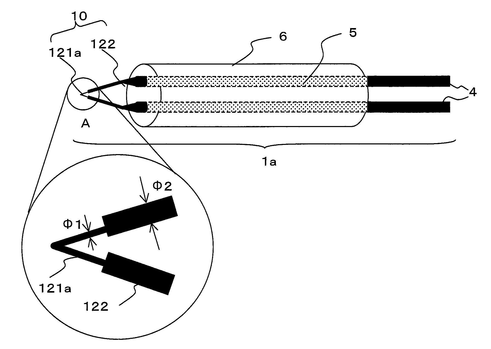
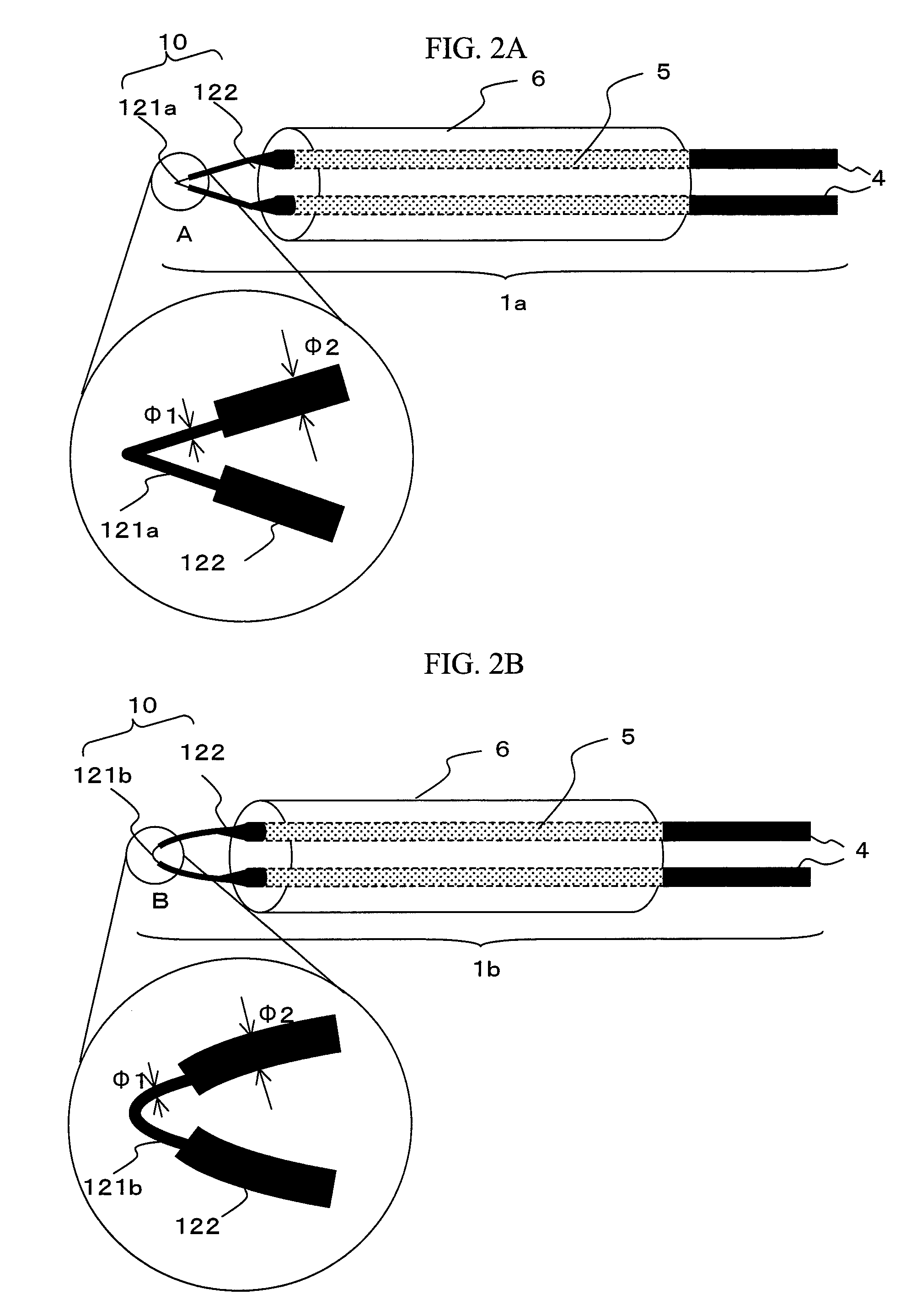
[0042]In the first embodiment, an explanation will be made with reference to FIG. 2A and FIG. 2B, as to the probe having a system to heat a sample, by using Joule heat that is generated when energizing a metallic wire.

[0043]FIG. 2A is a schematic illustration of the micro sample heating probe 1a that employs a metallic wire with an acute-angled tip, and FIG. 2B is a schematic illustration of the micro sample heating probe 1b that employs a metallic wire with a circular-arc shaped tip. In the following description, both of the probes above are referred to as the micro sample heating probe 1, unless otherwise distinguished.

[0044]The heated parts 121a and 121b are different only in shape. Therefore, firstly, a common property will be explained, naming these elements generically as “heated part 121”. As for the shape, it will be described later.

[0045]The micro sample heating probe 1 is provided with a sample holder 10 for holding the micro sample, a supporting part 6 for supporting the ...

second embodiment

[0085]Next, there will be explained a method of making the micro sample heating probe 1, having the heated part 121 with the diameter made up of multiple steps, which has been explained in the first embodiment of the present invention.

[0086]As a wire of the heated part 121a of the micro sample heating probe 1a relating to the present embodiment, a wire referred to as “Wollaston wire” is employed, which is made by coating a thin Pt wire with Ag. This wire has a structure that Pt of φ5 μm is embedded into the center of the Ag wire of φ80 μm. The sample holder 10 having the heated part 121a is formed by the use of this wire.

[0087]Firstly, the wire as described above is molded into a shape of the sample holder 10, and it is connected to the probe. Then, only the tip of the sample holder 10, which corresponds to the heated part 121a, is dipped into HNO3 solution. Ag dissolves in HNO3 solution, but Pt does not dissolve therein. Therefore, only Ag coating Pt is removed and Pt is exposed.

[0...

third embodiment

[0093]Next, another method of making the heated part 121 will be explained with reference to the accompanying drawings.

[0094]Firstly, as shown in FIG. 4A, a probe on which a wire is mounted is produced, the wire not being connected at the tip of the sample holder 10.

[0095]Here, it is assumed that the material of the tip wire is Cu, the diameter is 1 mm, and the exposed part of the wire is approximately 10 mm in length.

[0096]Next, as shown in FIG. 4B, Ag paste 50 is applied to the wire tip of φ1 mm.

[0097]Then, as shown in FIG. 4C, a thin wire, which is processed into v-shape in advance for the heated part 121a, is connected to the probe tip via the Ag paste 50.

[0098]The material of the thin wire connected to the probe tip is Pt, and the diameter is set to φ10 μm. It is to be noted here that the length of the heated part 121a is approximately 2 mm.

[0099]Those operations described above can be performed under the stereoscopic microscope with a magnification of around 30 times.

[0100]In ...


PUM

PropertyMeasurementUnit
surface areaaaaaaaaaaa
volumeaaaaaaaaaa
thicknessaaaaaaaaaa

Abstract

An object of the present invention is to extract a micro foreign body of a few μm, which may cause a product defect of a device or the like, and to subject the foreign body to a mass analysis at a favorable S / N ratio without any contamination. A micro sample heating probe includes a sample holder made up of two members different in diameter, a supporting part, and a terminal part. The sample holder includes a heating mechanism only in a limited part, and just a region extremely close to the micro sample being an analysis target is heated locally. Therefore, even when a contaminated substance is attached to the probe, such substance is not heated, thereby preventing a noise from occurring, and enabling an analysis at a quite favorable S / N ratio.

Description

FIELD OF THE INVENTION[0001]The present invention relates to a micro sample heating probe and a method of making the same, and an analyzer and an analytical method using the micro sample heating probe.DESCRIPTION OF THE RELATED ART[0002]A micro fine particle of a few μm, which is generated during a process for manufacturing a precision electronic device, is a critical problem that may cause a product defect. In particular, in a step for manufacturing a liquid crystal display, which heavily uses organic materials, a micro foreign body of polymer organic substance may cause a deterioration of yield.[0003]Mass spectrometry is effective for identifying an unknown organic compound. Since the mass spectrometry requires vaporization and ionization of a sample, if the sample is refractory, such as the polymer organic substance, the sample has to be rapidly heated for thermal decomposition.[0004]In the mass spectrometry as described above, it is desirable to extract and isolate the micro for...

Claims


Application Information

Patent Timeline
Patent Type & Authority Applications(United States)
IPC IPC(8): H01J49/26G01N30/02
CPCH01J49/16H01J49/0459
Inventor HORIKOSHI, KAZUHIKOAKAMATSU, NAOTOSHIOTANI, TOSHIAKI
Owner HITACHI LTD
Why Eureka
Try Eureka