Method and apparatus for measuring in-situ stress of rock using thermal crack

Inactive Publication Date: 2009-03-12
KOREA INST OF GEOSCI & MINERAL RESOURCES
View PDF6 Cites 19 Cited by
  • Summary
  • Abstract
  • Description
  • Claims
  • Application Information

AI Technical Summary

Benefits of technology

[0014]The method for measuring in-situ stress in rock using a thermal crack according to the present invention has an advantage in that the in-situ stress in the rock, i.e., the maximum and minimum horizontal stresses as well as the vertical stress, can be precisely measured, compared to a conventional hydraulic fracturing method.
[0015]Further, the method for measuring in-situ stress in rock using a thermal crack according to the present invention has another advantage in that in-situ stress can be easily measured.
[0016]In addition, the apparatus for measuring in-situ stress in rock using a thermal crack according to the present invention can measure the in-situ stress in rock at a great depth, and can be easily used due to simple configuration thereof.

Problems solved by technology

This is because no underground structure can be designed and constructed in a stable and economical manner inside rock until the direction and magnitude of stresses acting on the rock have been accurately measured.
For instance, when excavating a tunnel without exactly measuring the in-situ stress in the rock, the rock may become overstressed due to stress concentration on an excavated surface and may collapse or become unstable due to expansion of existing cracks.
Among the methods for measuring in-situ stress in rock, hydraulic fracturing has an advantage in that it can be applied to deep underground rock as long as the borehole can be drilled, but has a disadvantage in that it is not easily applied to specific types of rock, for instance, sedimentary rock with a stratified structure.
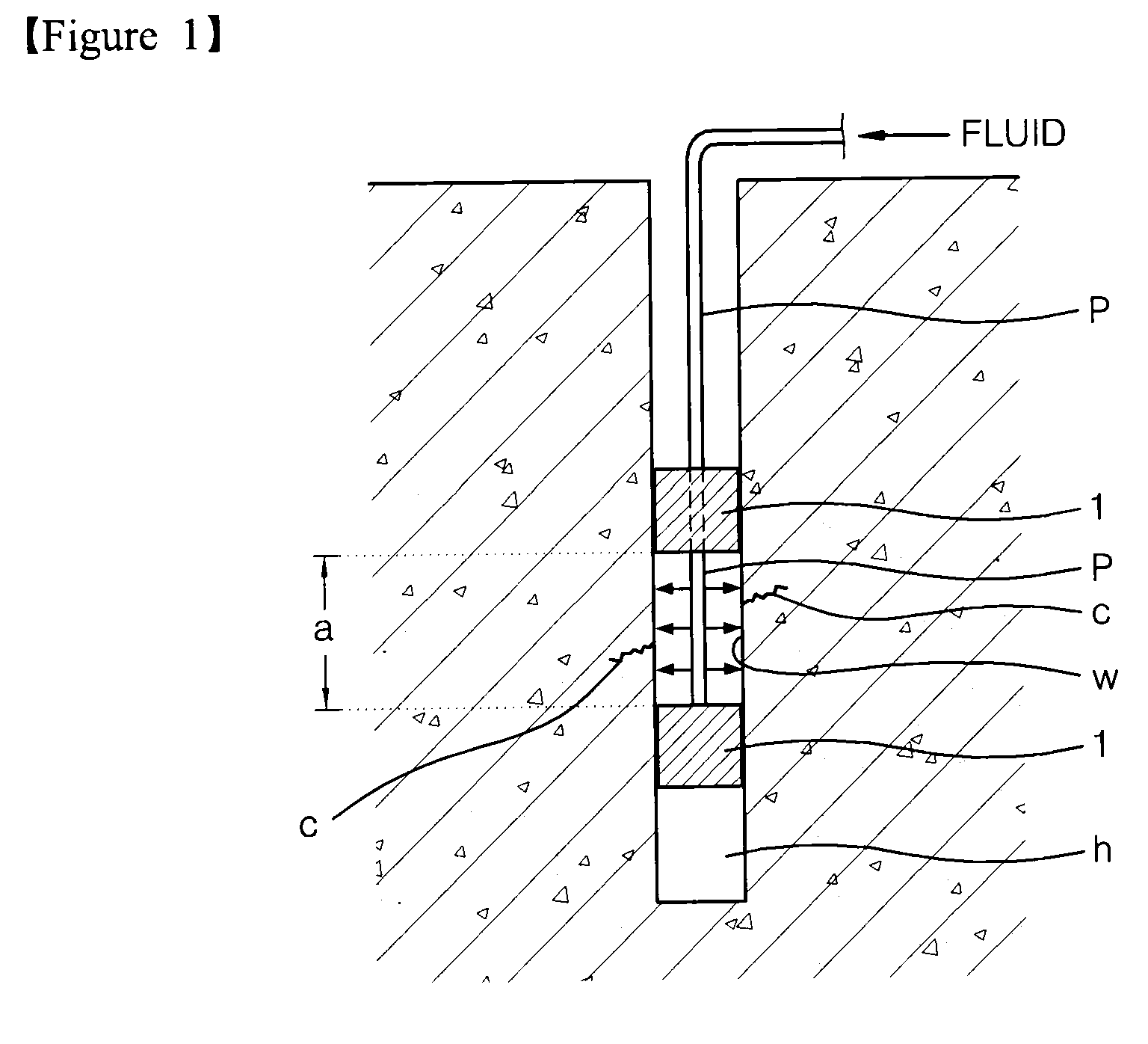
Further, when pressure is applied using packers 1, the borehole may collapse or the packers may jam.
This complicates withdrawal of equipment, especially at greater depths.
Further, since the size of the equipment must be increased in order to apply high hydraulic pressure, there are difficulties in using the conventional hydraulic fracturing system.
As described above, hydraulic fracturing has a limitation in that only two parts of principal stress can be measured.
In other words, hydraulic fracturing has a limitation in that, since the vertical stress is set to the surface load (density*mass*height), the maximum and minimum principal stress can be measured in only a horizontal direction, and thus in-situ stress cannot be accurately measured.
Furthermore, many researchers who have extensively studied hydraulic fracturing cast a doubt on the accuracy of crack re-opening pressure as well as the variation in pore hydraulic pressure in cracks (Ito et al., 2001).
However, since overcoring is based on the measurement of strain, it requires elaborate dual coring work.
Hence, when applied, overcoring is problematic in that it is highly complex as well as restricted to the depth of the borehole.

Method used


Image

  • Method and apparatus for measuring in-situ stress of rock using thermal crack
  • Method and apparatus for measuring in-situ stress of rock using thermal crack
  • Method and apparatus for measuring in-situ stress of rock using thermal crack

Examples


Embodiment Construction

]

[0047]Hereinafter, an apparatus for measuring in-situ stress in rock using a thermal crack according to an exemplary embodiment of the present invention will be described with reference to the accompanying drawings, and than a measuring method using the apparatus will be described in greater detail.

[0048]FIG. 4 is a schematic view illustrating an apparatus for measuring in-situ stress in rock using a thermal crack according to an exemplary embodiment of the present invention, wherein FIG. 4A shows the state in which a coolant container is expanded, and FIG. 4B shows the state in which a coolant container is contracted. FIG. 5 is a schematic cross-sectional view taken along line V-V of FIG. 4A. FIG. 6 is an exploded perspective view illustrating the coolant container, the main part of the in-situ stress measuring apparatus illustrated in FIG. 4.

[0049]Referring to FIGS. 4 through 6, an apparatus 100 for measuring in-situ stress in rock using a thermal crack according to an exemplary ...


PUM


Abstract

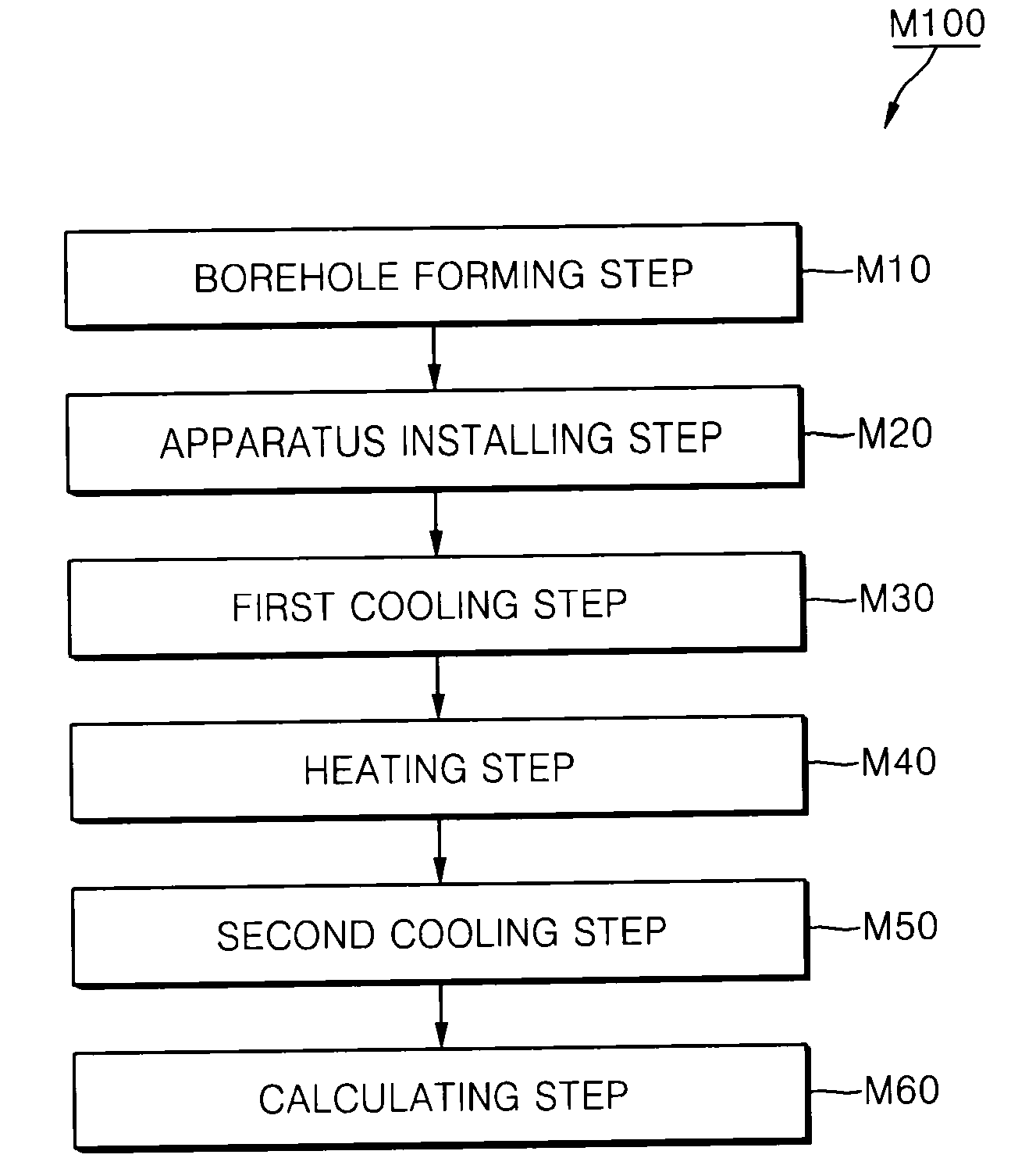
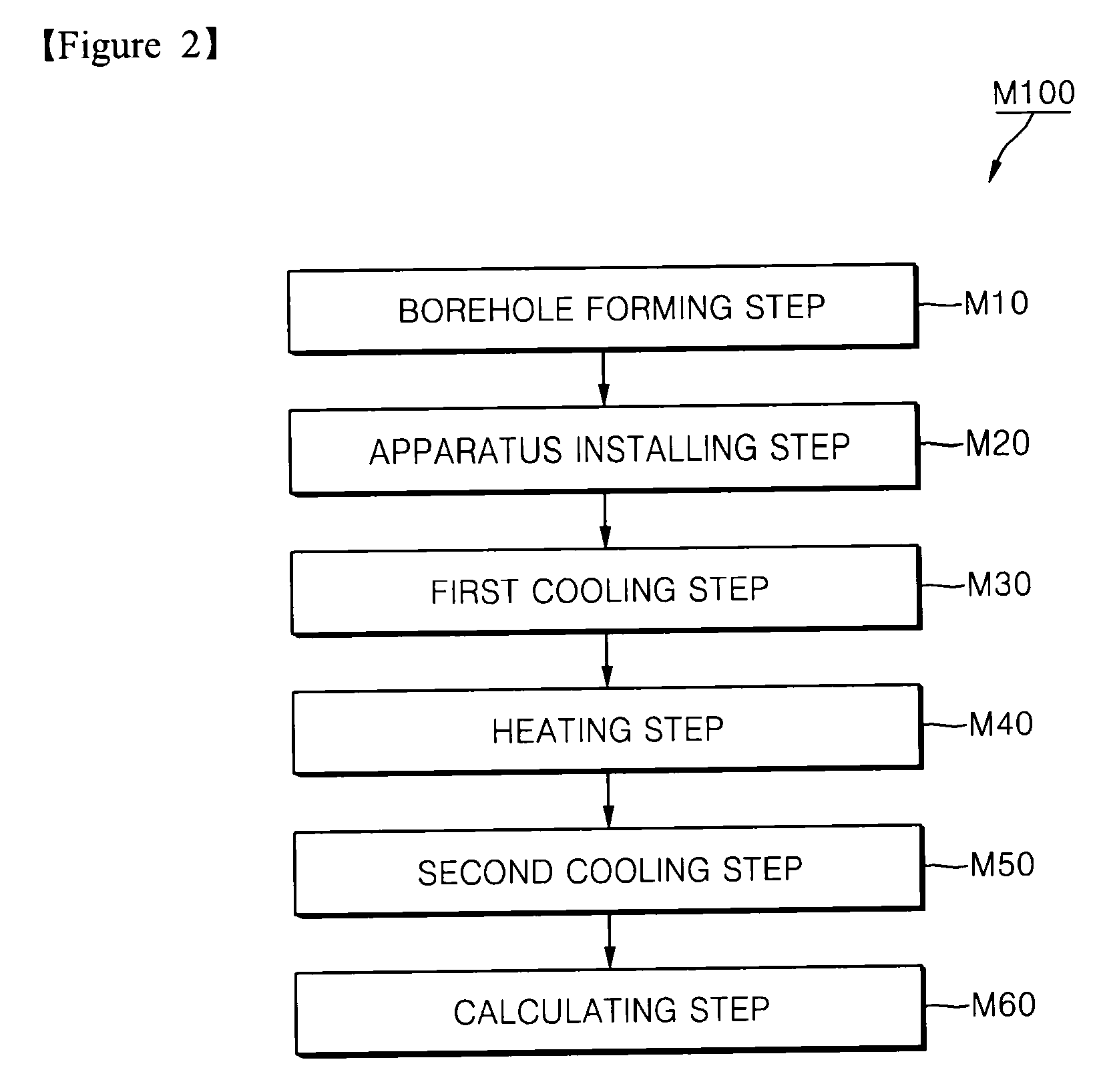
Disclosed is a method and apparatus for measuring in-situ stress in rock using a thermal crack. The method involves forming a borehole, cooling a wall of the borehole, applying tensile thermal stress, forming a crack in the borehole wall, and measuring temperature and cracking point. Afterwards, the borehole wall is heated to close the formed crack, the borehole wall is cooled again to re-open the crack, and temperature is measured when the crack is re-opened. The in-situ stress of the rock is calculated using a first cracking temperature at which the crack is formed and a second cracking temperature at which the crack is re-opened. Further, the apparatus cools, heats and re-cools the borehole wall, thereby measuring the first cracking temperature, the second cracking temperature, and the cracking point.

Description

TECHNICAL FIELD[0001]The present invention relates to a method and apparatus for measuring in-situ stress in rock, and more particularly, to a method and apparatus for measuring in-situ stress in rock, in which the in-situ stress in rock is measured by applying heat to the rock using a cryogenic coolant to thereby generate cracks.BACKGROUND ART[0002]The term “in-situ stress in rock” refers to stress that exist in the interior of rock, including gravitational stress, tectonic stress, and residual stress. Here, gravitational stress indicates stress generated by the rock's own weight. Tectonic stress indicates stress generated by movement of the earth's crust. Residual stress indicates stress remaining after removal of its original cause, such as expansion or heating of the rock or a past surface load since removed by surface erosion.[0003]In the design or safety analysis of a large-scale structure in rock such as a tunnel or an oil storage tank, calculation of in-situ stress in the ro...

Claims


Application Information

Patent Timeline
IPC IPC(8): G01L1/00G06F19/00
CPCE21B49/006E21B43/26E21B43/2605G01L1/00G01N25/00G01B21/32
Inventor RYU, CHANG-HARYU, DONG-WOOCHOI, BYUNG-HEEJOHN, LOUI PORATHURSYNN, JOONG-HO
Owner KOREA INST OF GEOSCI & MINERAL RESOURCES
Why Eureka
Try Eureka