Duplicate Transmission Path Switching Device

Inactive Publication Date: 2009-03-12
MEDIA GLOBAL LINKSKK
View PDF6 Cites 5 Cited by
  • Summary
  • Abstract
  • Description
  • Claims
  • Application Information

AI Technical Summary

Benefits of technology

[0016]According to the duplicate transmission path switching apparatus of the present invention, it becomes possible to carry out non-interruption switching from the master transmission path to the backup transmission path in the case of transmission error such as abnormal signal level of received packet, a packet-drop, packet-drops of more than a predetermined number, or a time-out of receiving packet.

Problems solved by technology

Further, the method disclosed in Jpn. patent No. 2874112 is characterized in that an error such as bit error in data block is detected, and switching control signal is generated.
However, in the switching disclosed in Jpn. patent No. 2874112, the switching is not carried out in the case of an unrecognized error such as the case of an IP packet-drop or the case where the packet is not received within a predetermined period of time.

Method used


Image

  • Duplicate Transmission Path Switching Device
  • Duplicate Transmission Path Switching Device
  • Duplicate Transmission Path Switching Device

Examples


first embodiment

[0042]Hereinbelow, a first embodiment will be described.

[0043]

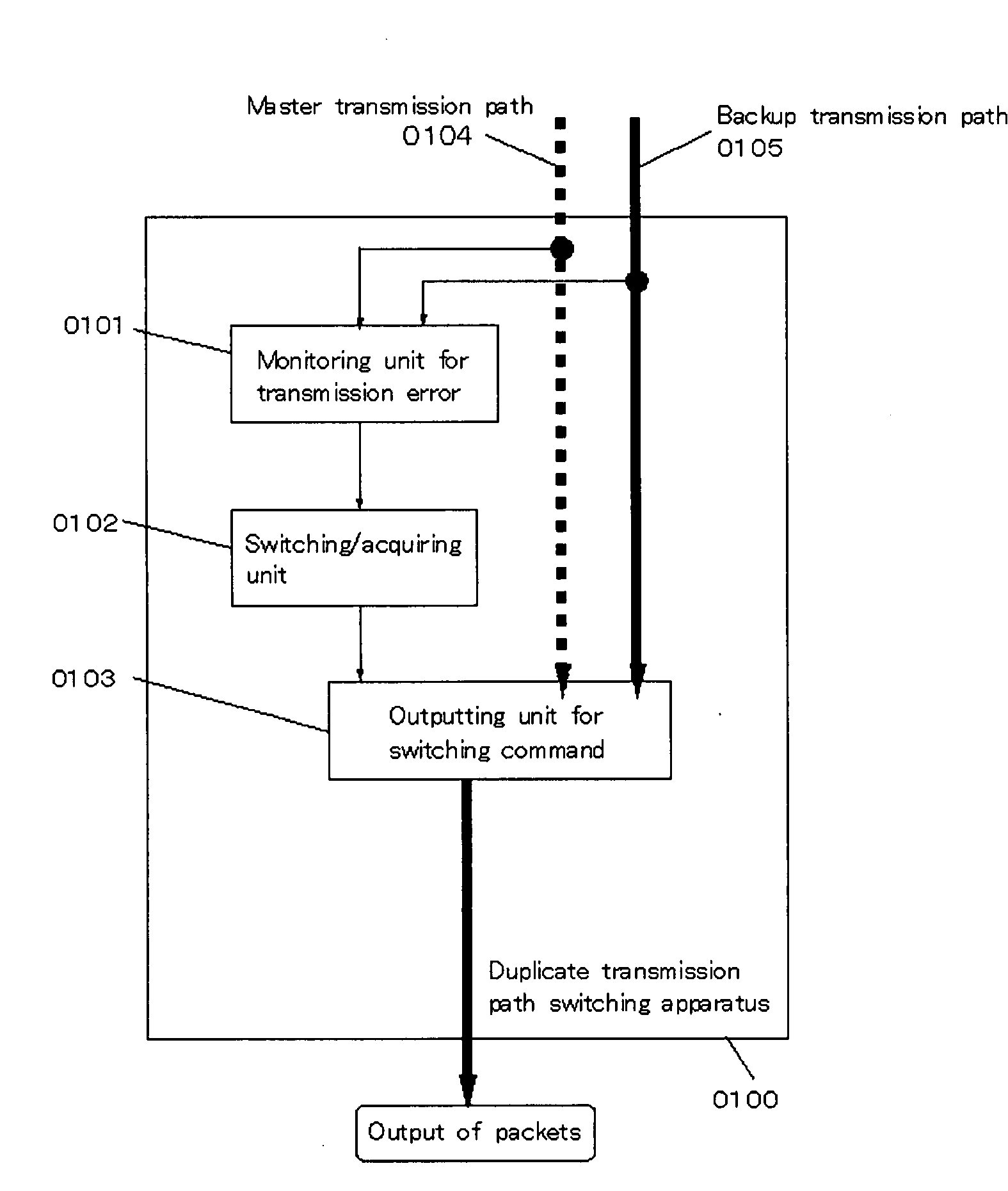
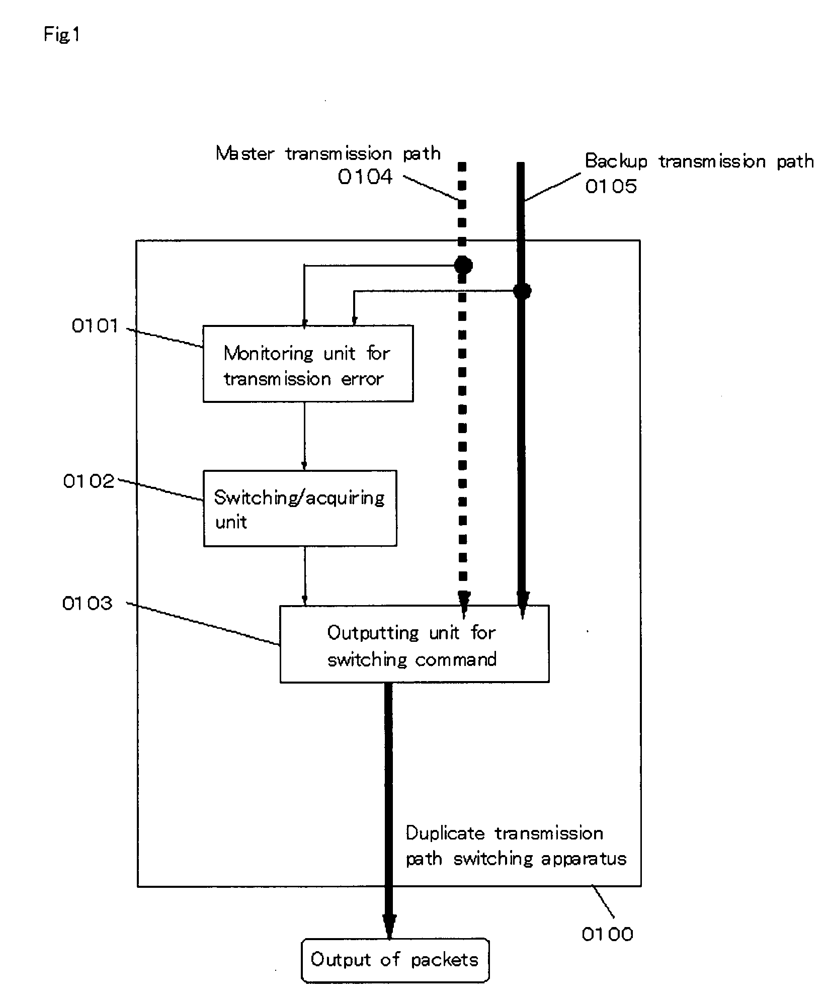
[0044]Hereinbelow, a concept of the first embodiment will be described. According to the duplicate transmission path switching apparatus of the first embodiment, if a transmission error such as a packet-drop or packet time-out occurs, switching from the master transmission path to the backup transmission path is carried out, so that continuity of communication is ensured. Specifically, this is effective for data required to have continuity such as video data.

[0045]

[0046]Hereinbelow, the components of the first embodiment will be specified.

[0047]FIG. 1 is a functional block diagram exemplifying the duplicate transmission path switching apparatus the first embodiment. A duplicate transmission path switching apparatus 0100 comprises a monitoring unit for transmission error 0101, an output unit for switching command 0102, a switching / acquiring unit 0103, a master transmission path 0104, and a backup transmission path 0105. No...

first example

[0070]Hereinbelow, a first example of the first embodiment will be described. In the first example, the case where the transmission error is the ‘abnormal signal level of received packet’ will be described.

[0071]FIG. 3 is a functional block diagram exemplifying the duplicate transmission path switching apparatus the first example. A duplicate transmission path switching apparatus 0300 comprises a monitoring unit for transmission error 0301, an output unit for switching command 0302, a switching / receiving unit 0303, a master transmission path 0304, and a backup transmission path 0305.

[0072]At the outset, the monitoring unit for transmission error monitors the received packets 1, 2, 3, and 4 from the master transmission path (packets surrounded by perforated lines in FIG. 3, and the perforated lines indicate abnormal signal level of received packet). Subsequently, since the result of the monitoring by the monitoring unit indicates the transmission error for transmission error (abnorma...

second example

[0073]Hereinbelow, a second example of the first embodiment will be described. In the second example, the case where the transmission error is the ‘packet drop’ will be described.

[0074]FIG. 4 is a functional block diagram exemplifying the duplicate transmission path switching apparatus of the second example. A duplicate transmission path switching apparatus 0400 comprises a monitoring unit for transmission error 0401, an outputting unit for switching command 0402, a switching / receiving unit 0403, a master transmission path 0404, and a backup transmission path 0405.

[0075]At the outset, the monitoring unit for transmission error monitors the received packets 1, 2, and 4 from the master transmission path (packets surrounded by solid lines in FIG. 4, and the solid lines indicate that the received packets are normal). In this case, it is determined by monitoring packet numbers that the transmission error has occurred because the packet 3 has dropped. Subsequently, since the result of the...


PUM


Abstract

In switching by failure, no switching is performed when a packet of IP packet is lost or a packet has not arrived even when a predetermined time has elapsed, which are not recognized as a failure. There is provided a duplicate transmission path switching device for data packets having the same information configuration to a main transmission path and an auxiliary transmission path. The device includes a transmission failure monitoring unit for monitoring a transmission failure of the main transmission path; a switching receiving unit arranged at the downstream of the transmission failure monitoring unit capable of receiving a packet from the main transmission path during a normal mode, and switching to the auxiliary transmission path to acquire a packet from the auxiliary transmission path in a predetermined mode; and a switching command output unit used when the monitoring result shows that a transmission failure is present, for outputting a switching command capable of switching to the auxiliary transmission path before the transmission failure reaches the switching / receiving unit, to the switching / receiving unit.

Description

BACKGROUND OF THE INVENTION[0001]1. Field of the Invention[0002]The present invention relates to a duplicate transmission path switching apparatus, which can carry out non-interruptive switching in duplicate transmission, and a method of operation thereof.[0003]2. Description of the Related Art[0004]Conventionally, in the transmission path for communication (e.g., optical transmission path), if an error occurs in a transmission path currently being operated (hereinbelow, referred to as master transmission path), switching to a transmission path for backup of the master transmission path (hereinbelow, referred to as backup transmission path) and communication is carried out, so that continuity of communication is ensured. For example, in Jpn. patent No. 2874112, non-interruptive switching apparatus and method, in which the reduced requirement time from occurrence of the interruption to completion of the switching, is disclosed. Further, the method disclosed in Jpn. patent No. 2874112...

Claims


Application Information

Patent Timeline
IPC IPC(8): G06F11/07H04L69/40
CPCH04L1/22H04L41/0677H04L41/0663
Inventor MATSUSHIMA, HIROAKIHAYASHI, EIICHIMORITA, TAKAAKI
Owner MEDIA GLOBAL LINKSKK
Why Eureka
Try Eureka