
Tape drive system

a tape drive and head drive technology, applied in the field of tape drive systems, can solve the problems of head negatively affecting performance, the effect of wrapping the tape over the head during the tape drive operation, and inability to restrict the contact between the head and the tape,

Inactive Publication Date: 2009-03-12
IBM CORP
View PDF17 Cites 11 Cited by
  • Summary
  • Abstract
  • Description
  • Claims
  • Application Information

AI Technical Summary

Problems solved by technology

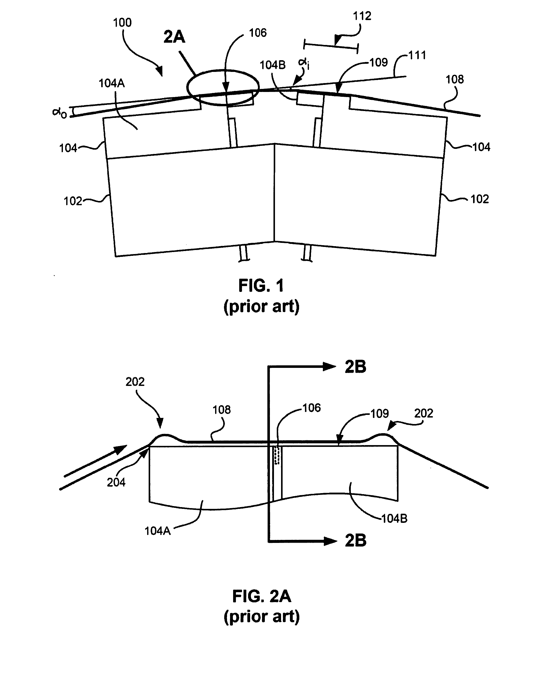
The current method of wrapping the tape over the head during tape drive operation does not in general allow constraining the contact between head and tape.
In addition, it is well known that wrapped configurations may produce considerable effects.
For example, spacing loss due to gap recession and debris accumulations on the head negatively affects performance.
These debris accumulations can sometimes cause shorting of critical head elements.
As tapes get smoother, stiction and running friction may become concerns.
Another difficulty can be tape shifting and dynamic skew.
Solutions such as coating tape heads may address one issue such as preventing shorting due to tape debris, but may cause increased susceptibility to stiction.
There are no known solutions that improve upon all of these concerns.
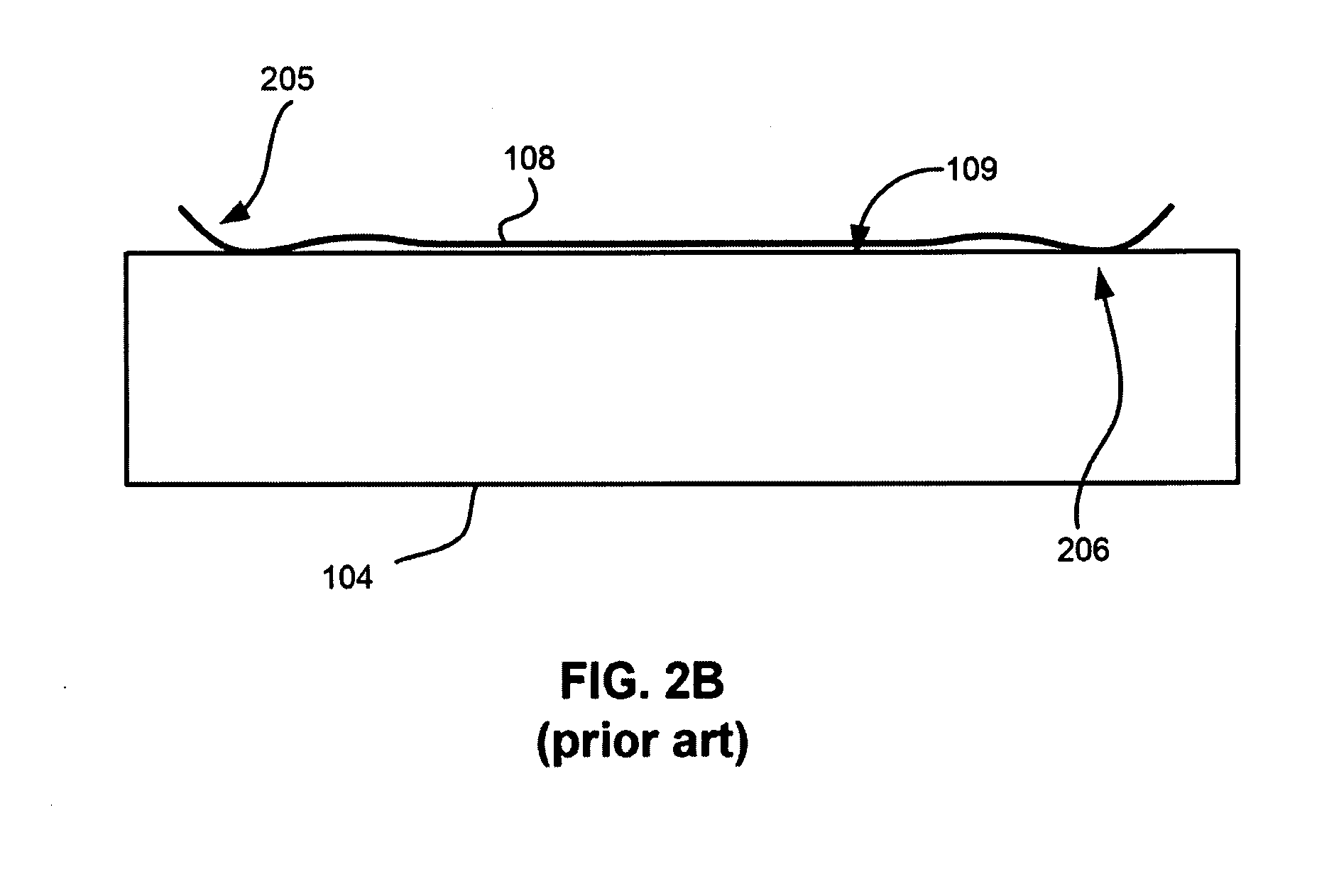
Particularly, the edges of the tape curl away from the tape bearing surface 109, resulting in edge loss or increased spacing between the edges of the tape and the tape bearing surface 109.
This is undesirable, as data cannot reliably be written to the edges of a tape in a system subject to edge loss.
Additionally, the tape lifting 205 results in additional stress at points 206 which, in turn, may cause additional wear.
Beyond this relatively unconstrained head-tape contact, which is largely due to air skiving, the tape itself is unconstrained against lateral transient disturbances in the free span between tape guides where the head is located.
These disturbances can produce mistracking between head and tape, and force, for example, cessation of the writing process.
Furthermore, other disturbances such as in tension can produce stick-slip conditions, mistracking and head-tape-spacing modulation.

Method used


Image

  • Tape drive system
  • Tape drive system
  • Tape drive system

Examples


Embodiment Construction

[0035]The following description is the best mode presently contemplated for carrying 5 out the present invention. This description is made for the purpose of illustrating the general principles of the present invention and is not meant to limit the inventive concepts claimed herein. Further, particular features described herein can be used in combination with other described features in each and any of the various possible combinations and permutations.

[0036]In the drawings, like and equivalent elements are numbered the same throughout the various figures.

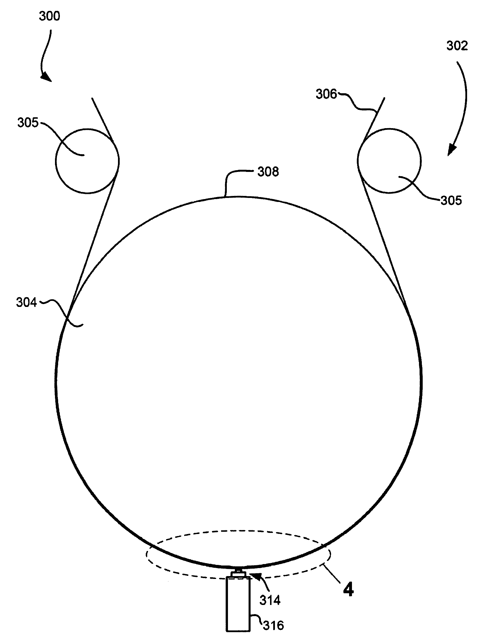
[0037]The embodiments described below disclose new tape drive systems that exhibit more constrained tape-head contact than systems such as those described with reference to FIG. 1. An embodiment of the present invention generally includes a support for engaging a tape; and a head directly opposing the support such that a tape engaging the support is positioned between the head and the support, the head being for performing at least...


PUM

PropertyMeasurementUnit
wrap angleaaaaaaaaaa
widthaaaaaaaaaa
rounded shapeaaaaaaaaaa

Abstract

A tape drive system according to one embodiment includes a support for engaging a tape; and a head directly opposing the support such that a tape engaging the support is positioned between the head and the support, the head being for performing at least one of reading from a tape and writing to a tape, wherein, during an operation period when the head is reading from or writing to a tape, the head is positioned such that at least one of the following occurs: the head does not contact the tape for a majority of the operation period; the head does not contact the tape for at least a portion of the operation period; and the head engages the tape for at least a portion of the operation period, the head pressing the tape towards the support when engaging the tape.

Description

FIELD OF THE INVENTION[0001]The present invention relates to tape drive systems, and more particularly, this invention relates to a tape drive system with at least partially constrained tape-head contact.BACKGROUND OF THE INVENTION[0002]Business, science and entertainment applications depend upon computing systems to process and record data. In these applications, large volumes of data are often stored or transferred to nonvolatile storage media, such as magnetic discs, magnetic tape cartridges, optical disk cartridges, floppy diskettes, or floptical diskettes. Typically, magnetic tape is the most economical, convenient, and secure means of storing or archiving data.[0003]Storage technology is continually pushed to increase storage capacity and storage reliability. Improvement in data storage densities in magnetic storage media, for example, has resulted from improved medium materials, improved error correction techniques and decreased areal bit sizes. The data capacity of half-inch...

Claims


Application Information

Patent Timeline
Patent Type & Authority Applications(United States)
IPC IPC(8): G11B5/56
CPCG11B5/52G11B5/00817
Inventor BISKEBORN, ROBERT GLENNLIANG, JASON
Owner IBM CORP
Learn More