Lens barrel, camera and mobile information terminal

Inactive Publication Date: 2009-03-12
RICOH KK
View PDF4 Cites 19 Cited by
  • Summary
  • Abstract
  • Description
  • Claims
  • Application Information

AI Technical Summary

Benefits of technology

[0023]Therefore, the present invention is possible to provide the lens barrel, the camera and the mobile information terminal capable of using the practically enough number of the cam followers and the cam grooves while the angle of rotation attained by those cam followers and cam grooves is also possible to be increased, and possible to obtain the high degree of freedom in the optical control and to achieve the stable drive.
[0024]More specifically, according to the lens barrel (1), it is possible to use the practically enough number of the cam followers and the cam grooves while the angle of rotation attained by those cam followers and cam grooves is also increased.
[0025]It is also possible to use the practically enough number of the cam followers and the cam grooves while the angle of rotation attained by those cam followers and cam grooves is also increased, by the lens barrel (2).
[0026]According to the lens barrel (3), in particular, it is possible to increase the angle of rotation effectively, and to achieve the stable drive.
[0027]According to the lens barrel (4), in particular, it is possible to effectively utilize a space behind the lens group supported by the lens frame in the photographing state.
[0028]According to the lens barrel (5), in particular, it is possible to achieve the stable drive and effectively avoid slant and displacement in the direction of the optical axis.

Problems solved by technology

Problems caused by such a type of structure include detachment of the cam followers from the cam grooves, deterioration of optical performance caused by a backlash or play between the cam followers and the cam grooves, generation of leakage of light, and so on.
Therefore, since a mechanism of the digital camera becomes complicated when the helicoid drive is employed, the helicoid drive is often not employed in digital cameras.
Therefore, there is a problem that the number of the helicoids is restricted when attempting to increase the angle of rotation, and thereby, further problems on the backlash, inclination of the lens barrel and so on arise due to unstable support of the lens frame.
On the other hand, when the number of the helicoids as the cam grooves is increased, the angle of rotation cannot be increased, and thus, a degree of freedom for performing optical control is limited.

Method used


Image

  • Lens barrel, camera and mobile information terminal
  • Lens barrel, camera and mobile information terminal
  • Lens barrel, camera and mobile information terminal

Examples


Embodiment Construction

[0147]Reference will now be made in detail to the present preferred embodiments of the present invention, examples of which are illustrated in the accompanying drawings. Wherever possible, the same reference numbers are used in the drawings and the description to refer to the same or like parts. The scope of the present invention, however, is not limited to these embodiments. Within the scope of the present invention, any structure and material described below can be appropriately modified.

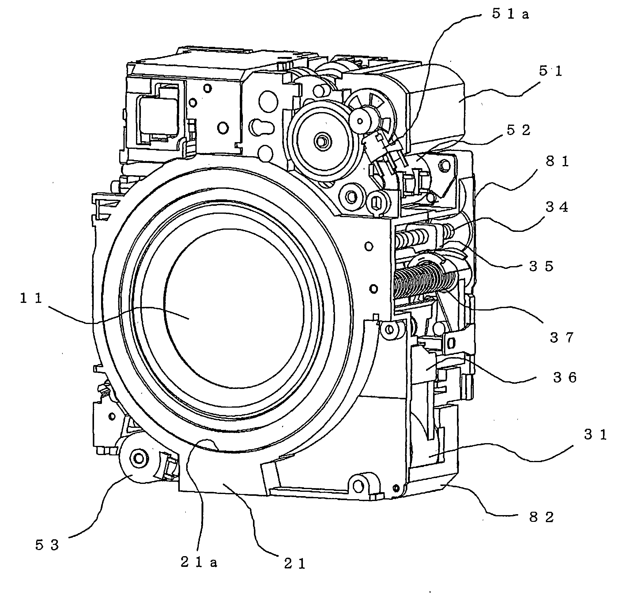
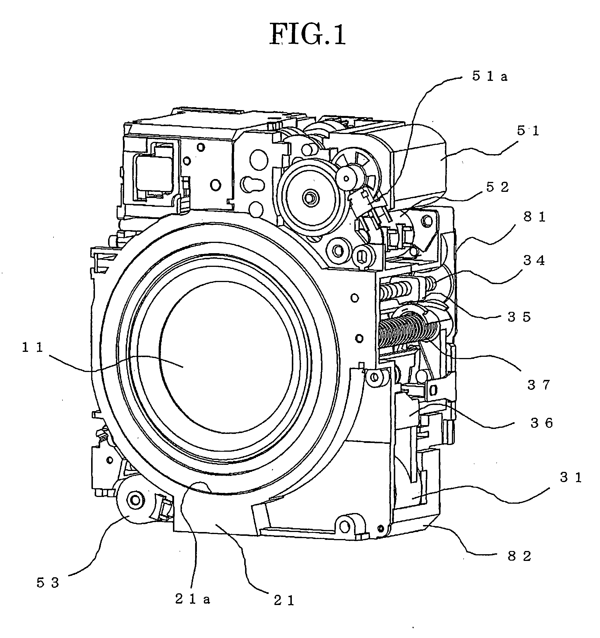
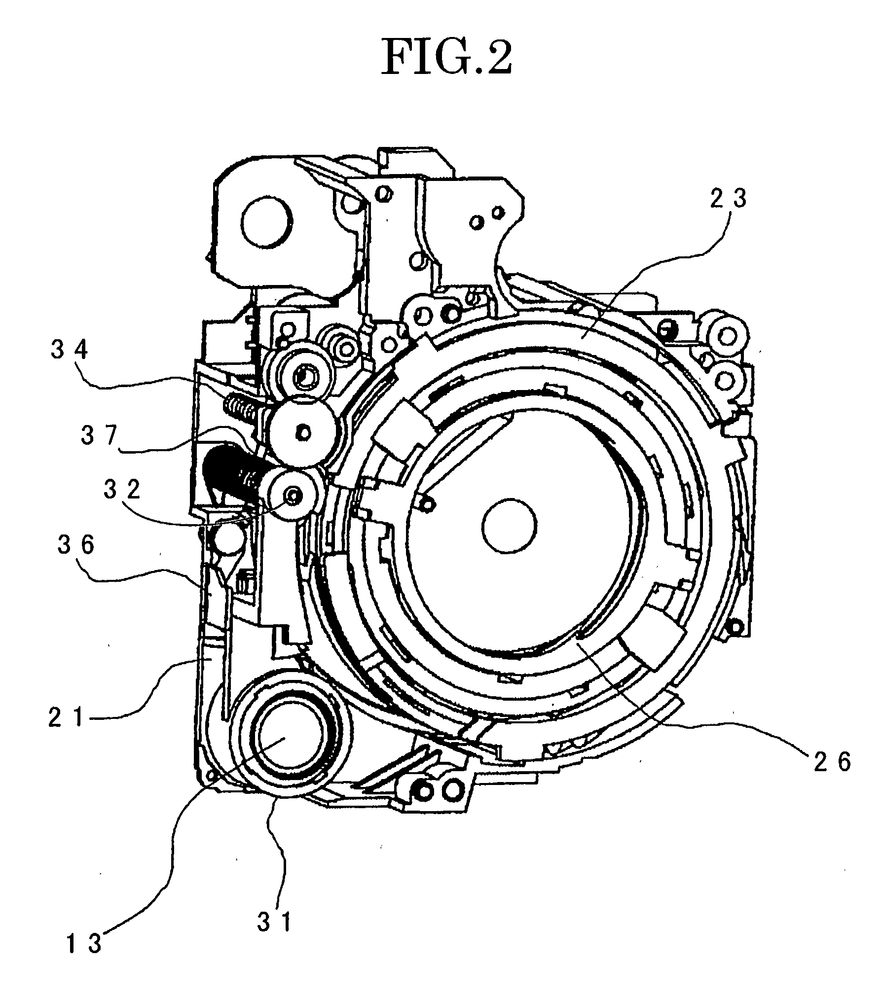
[0148]FIGS. 1 to 22 illustrate structures of main parts and various operational states of an optical system device including a lens barrel according to a first preferred embodiment of the invention.

[0149]In FIGS. 1 to 22, the lens barrel includes a fixed frame 21 having a fixed cylinder 21a, a telescopic cylinder unit or telescopic cylinder attached to the fixed frame 21, and a plurality of lens groups disposed in the telescopic cylinder. The telescopic cylinder is movable and collapsible along an...


PUM


Abstract

A lens barrel includes: a lens frame retaining at least one portion of the plurality of lens groups; a first lens cylinder supporting the lens frame inside thereof and including a plurality of cam followers on an outer circumferential section thereof; and a second lens cylinder including a mutually parallel plurality of cam grooves in an inner circumferential section thereof and storing the first lens cylinder therein in the collapsed state, the plurality of cam grooves are engaged with the plurality of cam followers and configured to advance and retire the first lens cylinder in a direction of an optical axis by a relative rotation of the first lens cylinder, the plurality of cam grooves have a first cam groove and a second cam groove, the plurality of cam followers have a first cam follower and a second cam follower, the first cam follower and the second cam follower are engaged with the first cam groove and the second cam groove, respectively, and the first cam follower and the second cam follower are disposed in positions mutually different relative to the direction of the optical axis.

Description

TECHNICAL FIELD[0001]The present invention relates to a lens barrel which establishes a collapsed state in which at least a part of a plurality of lens groups is collapsed to store the lens groups therein, and establishes a photographing state by moving at least a part of the plurality of lens groups toward a side of an object. More particularly, the invention relates to a lens barrel suitable for a photographing lens used for a camera such as a so-called digital camera, and to a camera and a mobile information terminal using the lens barrel.BACKGROUND ART[0002]A so-called digital camera, for example, which images an image of an object to be photographed with a solid-state image pick-up device such as a CCD (Charge-Coupled Device) image pick-up device or the like, acquires image data of a static image (still image) or a motion image (movie image) of the photographic object, and digitally stores the acquired image data into a recording medium such as a nonvolatile semiconductor memor...

Claims


Application Information

Patent Timeline
IPC IPC(8): H04N5/225
CPCG02B7/102G03B17/04G03B11/04G03B5/00G03B11/043G03B17/12G02B7/021
Inventor IWASAKI, TETSUYA
Owner RICOH KK
Why Eureka
Try Eureka