Reflector, an antenna using a reflector and a manufacturing method for a reflector
a technology of reflector and manufacturing method, which is applied in the direction of antennas, antenna details, antenna earthings, etc., can solve the problems of large weight and bulkyness of extruded profiles, and achieve the effect of low cost, low impedance across the tapering, and large capacitance between the taped sheet metal parts
- Summary
- Abstract
- Description
- Claims
- Application Information
AI Technical Summary
Benefits of technology
Problems solved by technology
Method used
Image
Examples
first embodiment
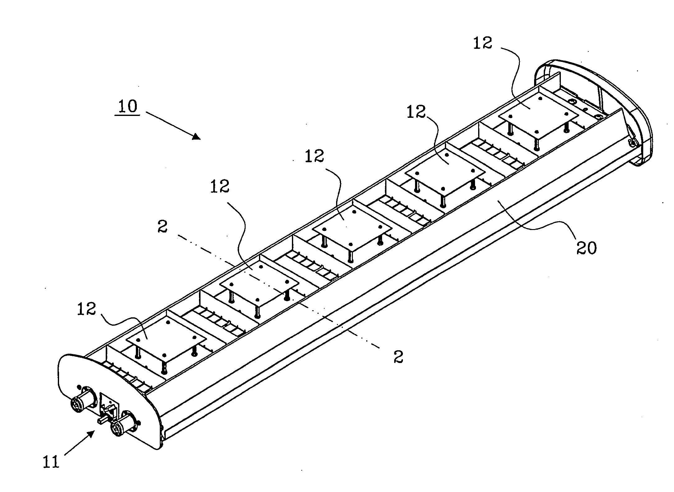
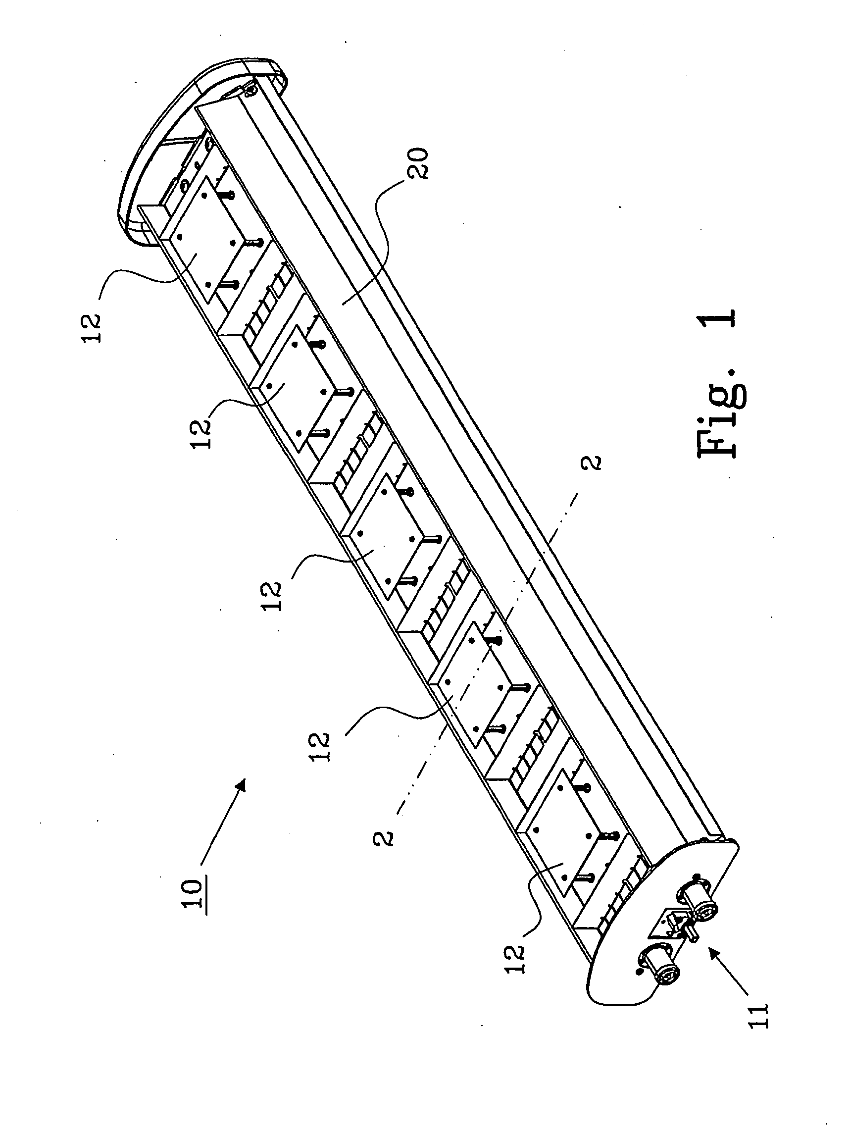
[0016]FIG. 1 shows a perspective view of an antenna 10, preferably used for mobile communication, with a reflector 20 according to the present invention. The antenna comprises input / output connections 11, for feeding signals to / from the antenna 20, antenna elements 12, for transmitting and receiving RF signals in different frequency bands, a distribution network (not shown), such as a phase-shifter, for distributing signals between the input / output connections 11 and respective antenna element 12, and a casing (not shown), mainly for protecting the antenna elements from the environment.
[0017]The antenna 10 comprises five antenna elements 12, but may comprise of fewer, or more, than that, e.g. only one antenna element is possible. In that case a distribution network is not necessary to distribute the signals within the antenna 10.
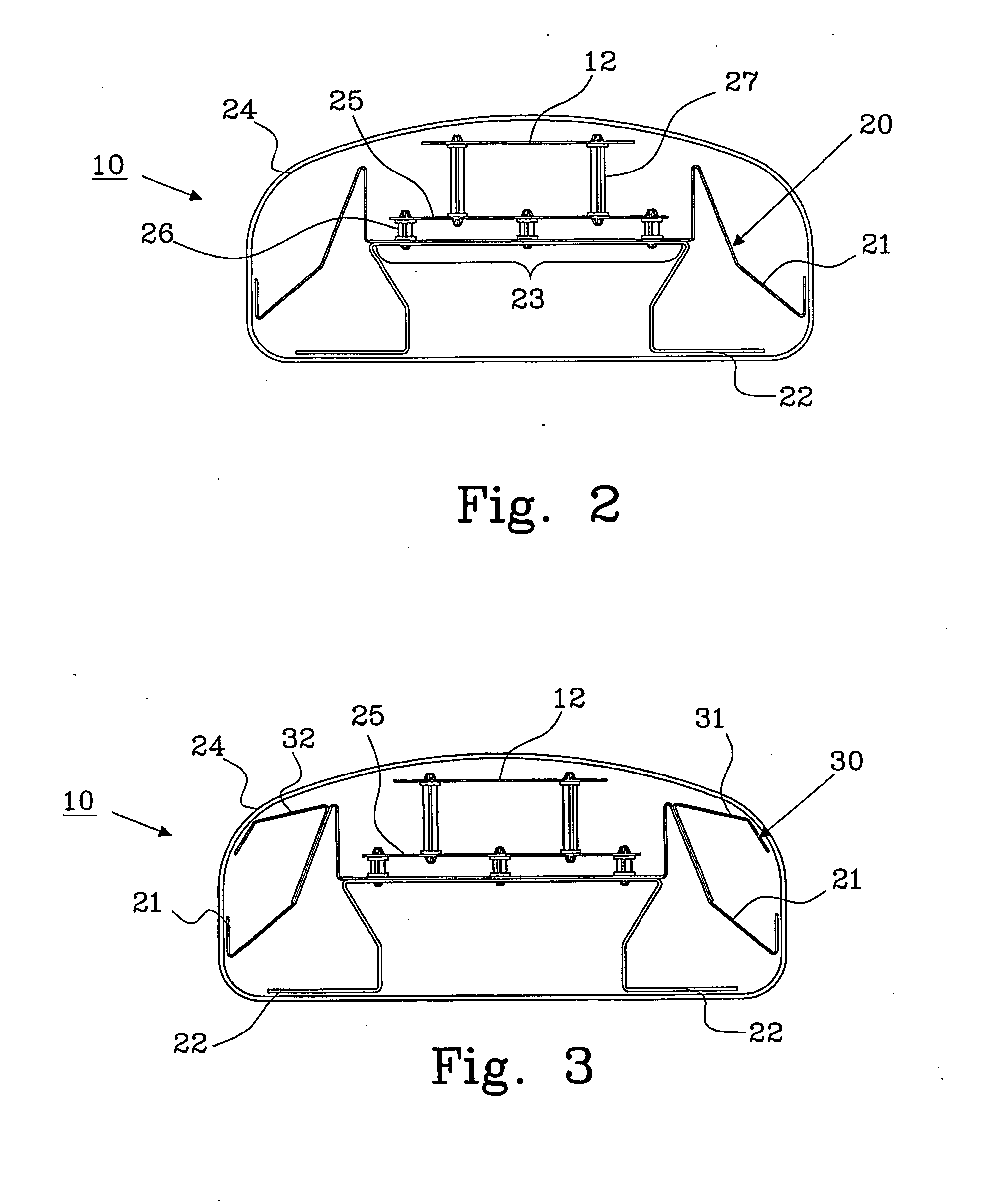
[0018]FIG. 2 shows a cross-sectional view of the antenna 10 in FIG. 1 along line 2-2. The reflector 20 of the antenna 10 comprises, in this first embodiment...
second embodiment
[0021]FIG. 3 shows a cross-sectional view of an antenna 10 with a reflector 30 according the present invention. The reflector 30 comprises a first part 21 and a second part 22, as described in connection with FIG. 2, a third part 31, which is electrically coupled to one side of the first part 21, and a fourth part 32, which is electrically coupled to a second side of the first part 21.
[0022]The antenna element 12 is arranged to the reflector 30 in a similar way as described in connection with FIG. 2, and a casing 24 is also provided surrounding the essential parts.
[0023]The third part 31 and fourth part 32 of the reflector 30 is electrically coupled to the first part 21 either indirectly or directly. An indirect coupling, such as a capacitive coupling, can be made by using a non-conductive adhesive, e.g. tape or glue, between the reflector parts 21 and 22. A direct electrical coupling can be achieved by spot welding, anodizing and bolting or by using a conductive adhesive.
third embodiment
[0024]FIG. 4 shows a cross-sectional view of a reflector 40 according to the present invention. The reflector 40 comprises two parts 41 and 42. This reflector is adapted to be mounted in an antenna that has a different loob pattern compared to the reflector described in FIGS. 1-3.
[0025]The loob pattern of the reflector shown in FIG. 4 has a 65 degrees 3 dB beam width and the reflectors shown in FIGS. 1-3 has 90 degrees 3 dB beam width.
[0026]FIG. 5 shows an alternative embodiment of an antenna 50 with the first embodiment of the reflector 20 according to the present invention. The casing of the antenna 50 comprises a base 51 and a cover 52. The second part 22 of the reflector 20 is integrated in the base 51 of the casing, and the first part 21 of the reflector 20 is electrically coupled to the second part 22 when mounting the antenna to its operating position in a communication mast.
PUM
 Abstract
Description
Claims
Application Information
 - R&D
- Intellectual Property
- Life Sciences
- Materials
- Tech Scout
- Unparalleled Data Quality
- Higher Quality Content
- 60% Fewer Hallucinations
Browse by: Latest US Patents, China's latest patents, Technical Efficacy Thesaurus, Application Domain, Technology Topic, Popular Technical Reports.
© 2025 PatSnap. All rights reserved.Legal|Privacy policy|Modern Slavery Act Transparency Statement|Sitemap|About US| Contact US: help@patsnap.com


