
Magnetron For Microwave Oven

a microwave oven and magneton technology, applied in the direction of magnetrons, transit tubes/containers, electric discharge tubes, etc., can solve the problems of cathode back heat by electrons, deterioration of load stability, and degradation of various characteristics of magnetrons

Active Publication Date: 2009-03-12
TOSHIBA HOKUTO ELECTRONICS CORP
View PDF10 Cites 9 Cited by
  • Summary
  • Abstract
  • Description
  • Claims
  • Application Information

AI Technical Summary

Benefits of technology

[0011]The above and other features and advantage of the present invention will become apparent from the discussion herein below of specific, illustrative embodiments thereof presented in conjunction with accompanying drawings, in which:
[0012]FIG. 1 is an enlarged cross sectional view around the anode cylinder of the magnetron for microwave oven according to an embodiment;
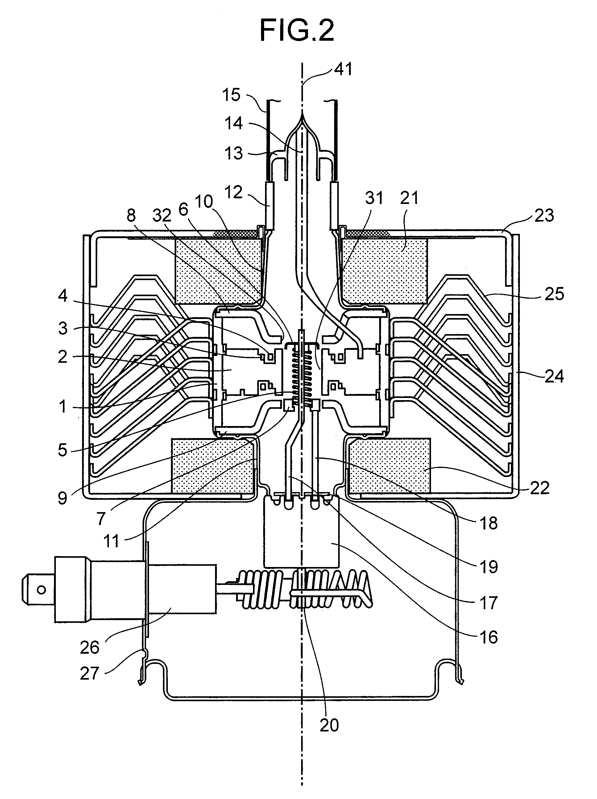
[0013]FIG. 2 is a cross sectional view of the magnetron for microwave oven according to an embodiment of the present invention; and
[0014]FIG. 3 is a table showing the shape and the characteristics of magnetrons for microwave oven.

Problems solved by technology

However, merely miniaturization would cause degradation of various characteristics of the magnetron.
For example, if the height of the vane in the direction of the axis and the length of the input stem portion are decreased, cathode back heat by electrons or deterioration of load stability may occur.
If the distance between both pole pieces is merely narrowed for the purpose of effective utilization of the magnet in order to reduce the height of the magnetron, electromagnetic coupling between the pole piece and the strap ring is increased and result in temperature rising of the cathode due to increase of cathode back heat by electrons.
On the other hand, if the height of the vanes in the direction of the axis is shortened to assure the distance between the pole piece and the strap ring to some extent, load stability may be deteriorated.
Furthermore, by digging the strap ring into inside the groove from the side end of the vane to decrease the electromagnetic coupling with the pole piece, cathode back heat by electrons and deterioration of the load stability rarely take place even if the height of the vanes in the direction of the axis or the input stem portion is diminished.
If the height of the vane in the direction of the axis is further decreased, it is conceivable that the load stability will be extremely deteriorated, so that the magnetron will not be suitable for practical use.
Thus, there is a possibility of deterioration of the output efficiency and melting of the pole piece, etc.
However, if the effective length of the filament is shortened, the load stability will deteriorate further and the cathode back heat by electrons will increase.

Method used


Image

  • Magnetron For Microwave Oven
  • Magnetron For Microwave Oven
  • Magnetron For Microwave Oven

Examples


Embodiment Construction

[0015]Hereinafter, embodiments of a magnetron for microwave oven according to the present invention will be described with reference to the drawings. The same symbols are given to same or similar configurations, and duplicated descriptions may be omitted.

[0016]FIG. 2 is a cross sectional view of the magnetron for microwave oven according to an embodiment of the present invention.

[0017]The magnetron for microwave oven of this embodiment has an anode cylinder 1, a cathode 5, a pair of end hats 6, 7, a pair of pole pieces 8, 9, which are located along the same axis (the central axis 41), and a plurality of vanes 2 extending radially from the proximity of the central axis 41.

[0018]The anode cylinder 1 extends cylindrically along the central axis 41. The vanes 2 extend radially from the proximity of the central axis 41, and fixed to the inner surface of the anode cylinder 1. Each of the vanes 2 is formed substantially as a rectangular plate. The free ends 31 of the vanes 2, which are not...


PUM


Abstract

A magnetron for microwave oven has an anode cylinder, vanes (height: H (mm)), a cathode spirally extending along the central axis, a pair of end hats (outer diameter: DEH1 (mm), DEH2 (mm)) fixed to both ends of the cathode, and a pair of pole pieces. Vanes extend from an inner surface of the anode cylinder to the central axis. Free ends of the vanes form a vane inscribing circle (diameter: Da (mm)). Pole pieces expand like funnels from through-holes (inner diameter: DPP1 (mm), DPP2 (mm)) facing to the end hats and pinch the cathode. The shape of the magnetron satisfies, H≦8.5, H / Da≦0.95, DEH1 / DPP1≦0.8, DEH1 / DPP2≦0.8, DEH2 / DPP1≦0.8, DEH2 / DPP2≦0.8, 0.92≦Da / DPP1≦0.95, and 0.92≦Da / DPP2≦0.95.

Description

CROSS REFERENCE TO RELATED APPLICATION[0001]This application is based upon and claims the benefit of priority from the prior Japanese Patent Application No. 2007-235511 filed on Sep. 11, 2007; the entire content of which is incorporated herein by reference.BACKGROUND OF THE INVENTION[0002]The present invention relates to a magnetron for microwave oven.[0003]An ordinary magnetron for microwave oven oscillating radio waves of 2450 MHz band is provided with an anode cylinder and a plurality of vanes. The vanes are radially arranged inside the anode cylinder. The vanes are alternately connected together in the direction of circumference by a pair of large and small strap rings soldered with the top and bottom ends of the vanes. A spiral cathode is located along the axis of the anode cylinder in the electronic interaction space surrounded by the free ends of the vanes. Both ends of the spiral cathode are fixed to the output side end hat and the input side end hat respectively. Furthermor...

Claims


Application Information

Patent Timeline
IPC IPC(8): H01J25/50
CPCH01J25/50H01J23/12H01J23/02
Inventor HIGASHI, MASATOSHI
Owner TOSHIBA HOKUTO ELECTRONICS CORP
Learn More