
Desuperheater muffler

a superheater and muffler technology, applied in the direction of valve details, valve arrangements, valve members for absorbing fluid energy, etc., can solve the problems of high construction and assembly cost of devices, high device complexity, and failure to meet the needs of use, so as to enhance evaporation of cooling water, enhance acoustic attenuation, and increase turbulence

Inactive Publication Date: 2009-03-12
CONTROL COMPONENTS INC
View PDF41 Cites 16 Cited by
  • Summary
  • Abstract
  • Description
  • Claims
  • Application Information

AI Technical Summary

Benefits of technology

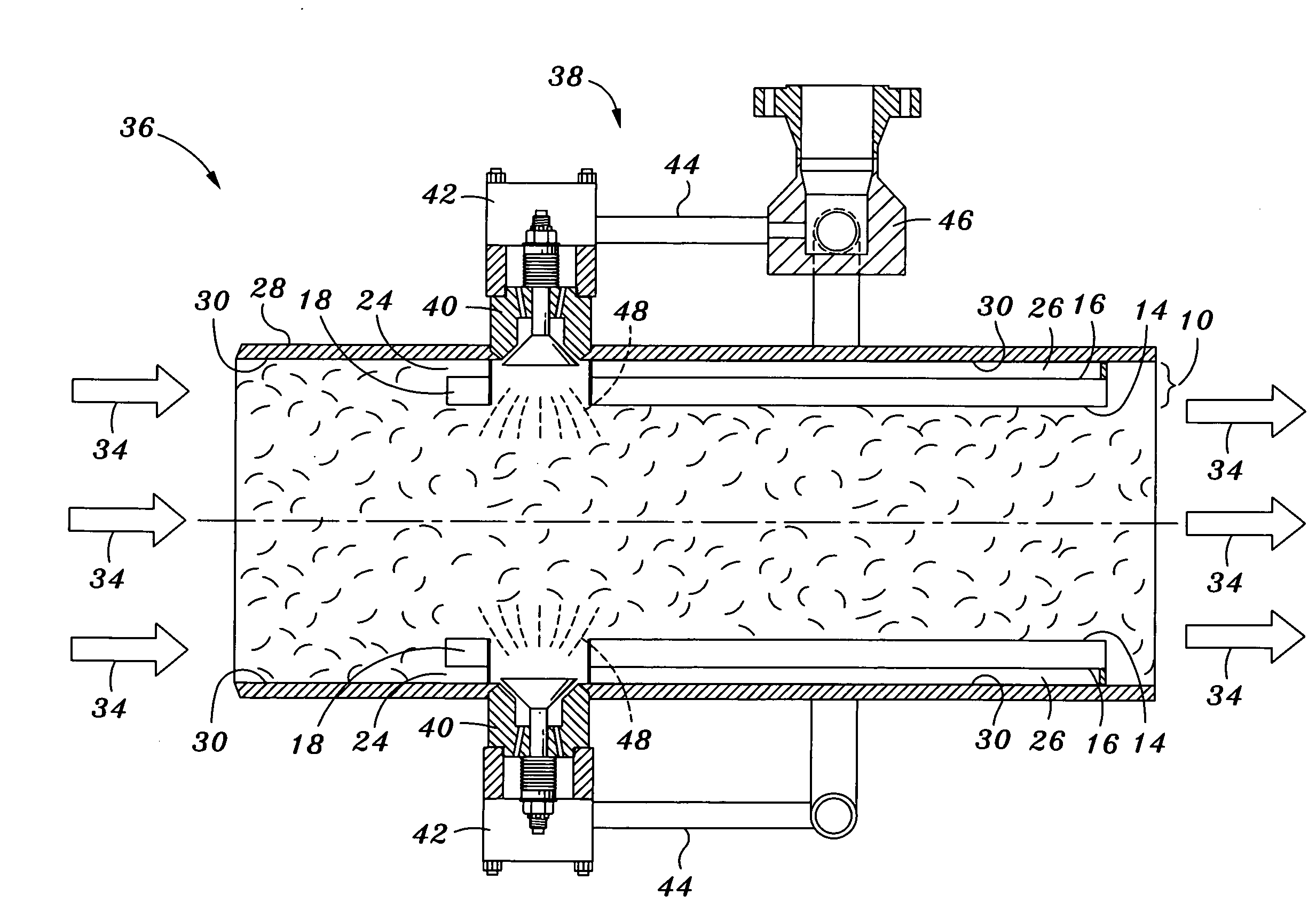
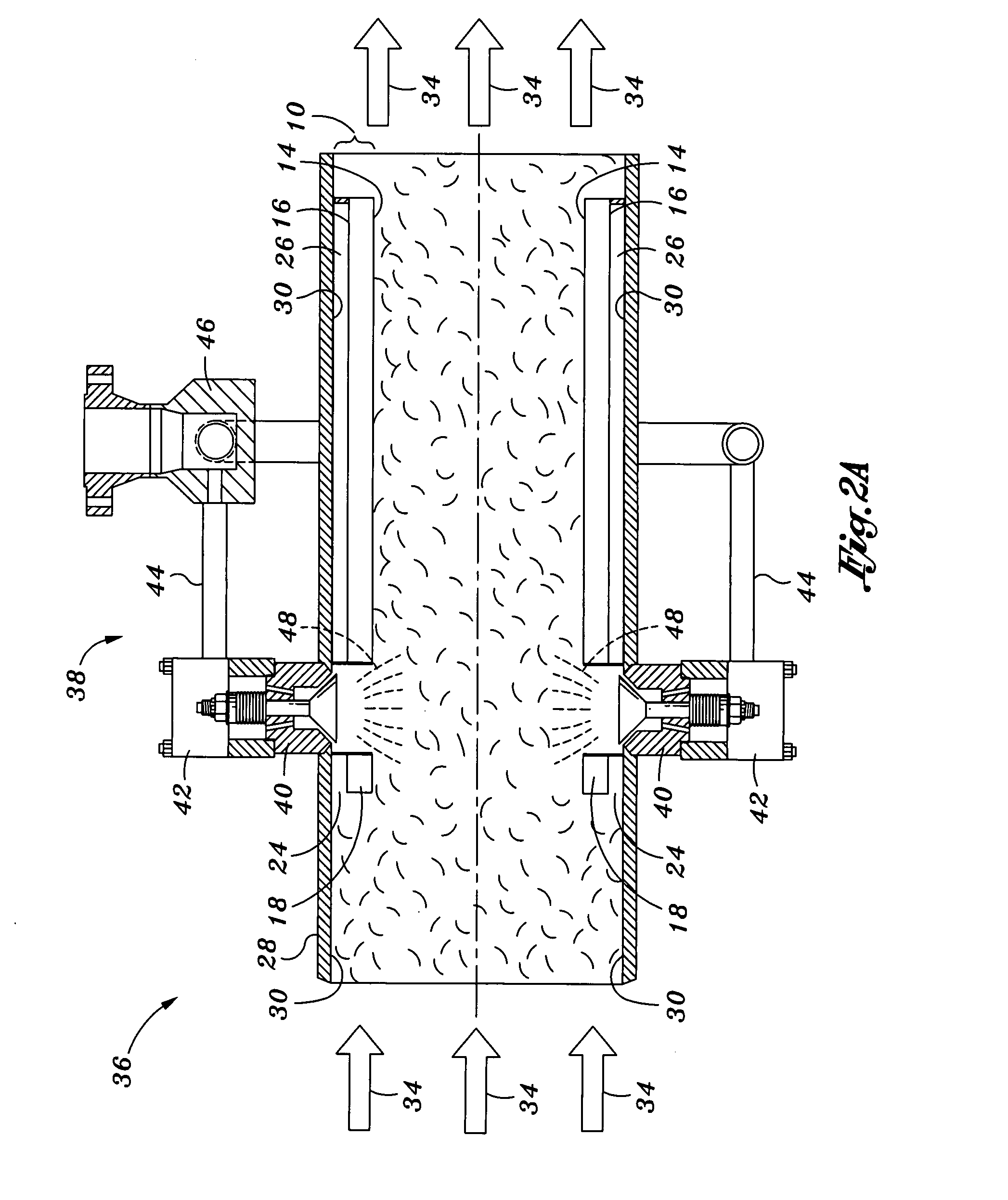
[0009]The liner system comprises a liner which is sized and configured to be positioned adjacent to an inner pipe wall of at least a portion of the steam outlet pipe in order to form a quarter-wavelength resonator cavity between an outer liner wall and the inner pipe wall for attenuating noise associated with the superheated steam flow. As mentioned above, the liner also prevents impingement of cooling water spray upon the inner pipe wall in order to reduce or prevent thermal shock to the steam pipe and any associated components.
[0010]The liner may further be configured to create a venturi effect within the flow of superheated steam to locally increase the velocity of the superheated steam flowing through the steam pipe and thereby enhance evaporation of the cooling water spray to improve cooling of the superheated steam. The liner is preferably coaxially mounted within the steam outlet pipe such that the cavity formed between an outer liner wall of the liner and the inner pipe wall of the steam pipe is annular in shape.
[0012]The liner may include a plurality of spaced perforations which preferably extend radially through a thickness of the liner. The cavity as well as the perforations are preferably sized and configured to promote the flow of superheated steam into the open end of the cavity such that the superheated steam entering the cavity is forced radially inwardly through the perforations into the main flow of superheated steam in order to enhance acoustic attenuation thereof. The flow of superheated steam through the perforations may also promote the venturi effect within the flow of superheated steam to enhance evaporation of the cooling water.
[0013]The inwardly directed flow of superheated steam through the perforations may further block the flow of cooling water into the perforations as well as increase turbulence in the main flow of steam passing through the steam pipe to enhance evaporation of cooling water. The perforations are preferably sized and configured to attenuate noise occurring within the steam outlet pipe. For perforated embodiments of the liner, porous material such as a wire mesh may be mounted within the cavity to prevent cooling water from flowing through the perforations toward the hot inner pipe wall and to enhance the acoustic effects of the annular cavity.

Problems solved by technology

Because superheated steam can damage turbines or other downstream components, it is necessary to control the temperature of the steam.
If the cooling water is sprayed into the superheated steam pipe in a streaming pattern, the spray of cooling water may impinge on the hot inner wall of the steam pipe resulting in the creation of thermal stresses and erosion in the steam pipe which, over time, may lead to structural failure.
However, the construction of this device is complex and includes many parts such that the device has a high construction and assembly cost.
Unfortunately, this device is also necessarily complex, costly to manufacture and install, and requiring a high degree of maintenance after installation.
Another problem associated with steam desuperheaters is noise control.
More specifically, noise that is associated with or that is generated by superheated steam flowing through a steam pipe can reach relatively high levels.
Such vent silencers and diffusers are typically installed as downstream components and are therefore generally ineffective in reducing noise associated with or generated by the flow of superheated steam.

Method used


Image

  • Desuperheater muffler
  • Desuperheater muffler
  • Desuperheater muffler

Examples


Embodiment Construction

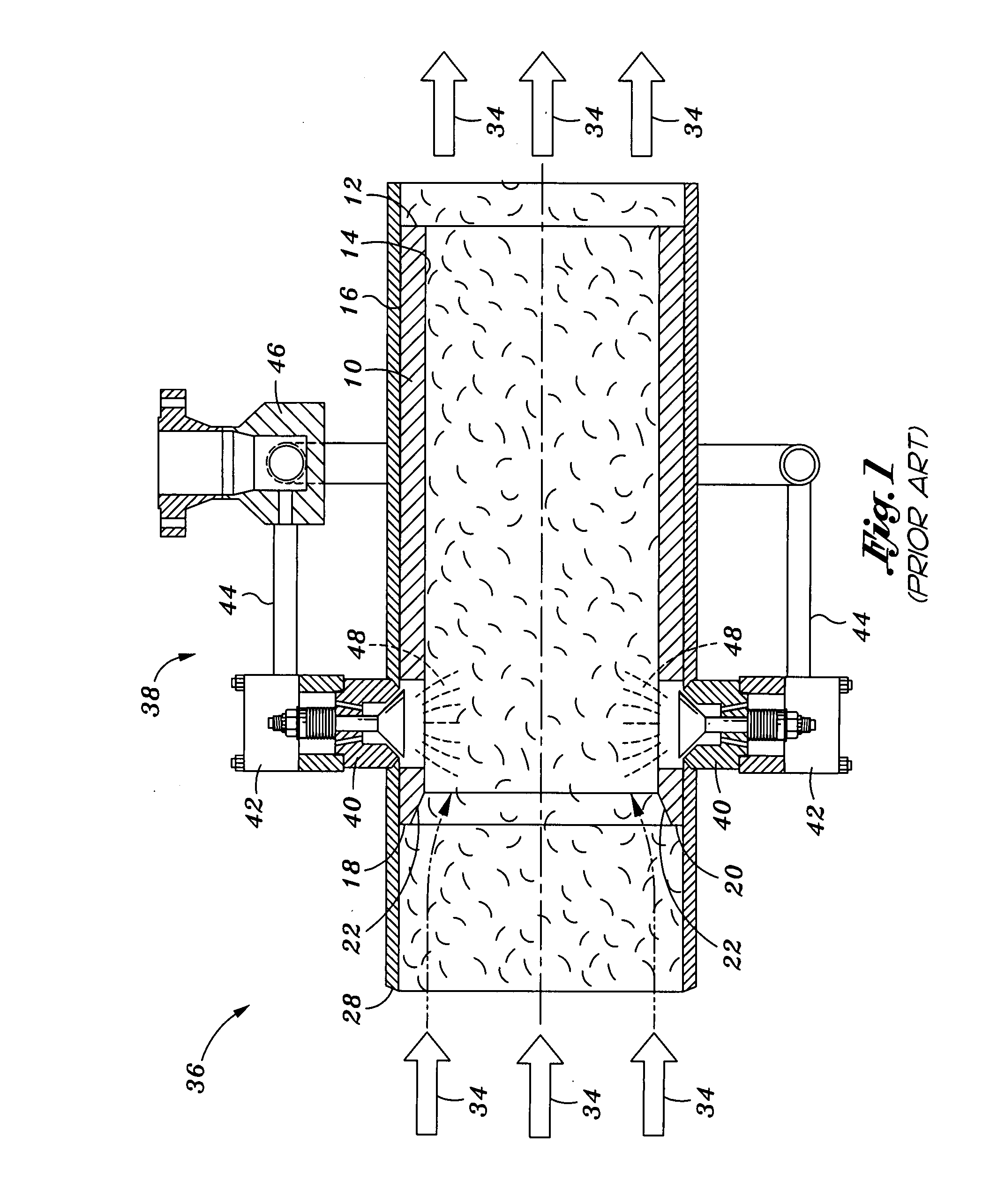
[0018]Referring now to the drawings wherein the showings are for purposes of illustrating preferred embodiments of the present of the invention and not for purposes of limiting the same, shown in the figures are longitudinal sectional views of a desuperheating device 38 incorporating a liner system 10. A prior art version of the liner system 10 is shown in FIG. 1 which illustrates a liner 14 wherein an outer liner wall 16 thereof is disposed in abutting contact with an inner pipe wall 30 of a steam pipe 28 of the desuperheating device 38. In contrast, FIGS. 2A-2B illustrate a liner system 10 of the present invention wherein the liner 12 is disposed in spaced relation to the inner pipe wall 30 such that an annular resonator cavity 24 is formed between the liner 12 and the steam pipe 28 for attenuating noise associated with a flow of superheated steam 34 passing through the steam pipe 28, as will be described in greater detail below.

[0019]The desuperheating device 38 may be constructe...


PUM


Abstract

A liner system for a steam outlet pipe of a turbine bypass system comprises a liner mounted in spaced coaxial relation to the inner pipe wall such that an annular cavity is defined between the liner and the steam outlet pipe. The cavity is open on an upstream end and closed on a downstream end such that a quarter-wavelength resonator is formed for attenuating noise associated with a flow of superheated steam passing through the steam pipe. The liner may include a plurality of perforations to further attenuate noise in the steam outlet pipe. The open upstream end and closed downstream end of the cavity increases pressure within the cavity to prevent cooling water from entering the perforations and contacting the inner pipe wall. A wire mesh disposed against the outer liner wall may block cooling water penetration through the perforations and may further attenuate noise associated with the flow of superheated steam.

Description

CROSS-REFERENCE TO RELATED APPLICATIONS(Not Applicable)STATEMENT RE: FEDERALLY SPONSORED RESEARCH / DEVELOPMENT(Not Applicable)BACKGROUND[0001]The present invention relates generally to steam desuperheaters and, more particularly, to a liner which is mountable within the interior of a steam pipe and which is specifically adapted to attenuate or reduce noise associated with a flow of superheated steam in the steam pipe while preventing damage to the steam pipe as a result of cold spray water impinging upon the hot inner surface of the steam pipe wall. The liner may further be configured to create a venturi effect within the steam pipe in order to increase the velocity of the steam relative to the cold spray water and thereby enhance evaporation of the spray water within the steam flow.[0002]Many industrial facilities operate with superheated steam that has a higher temperature than its saturation temperature at a given pressure. Because superheated steam can damage turbines or other do...

Claims


Application Information

Patent Timeline
Patent Type & Authority Applications(United States)
IPC IPC(8): F16L55/02
CPCF16L55/02781F16L55/02727
Inventor SHERIKAR, SANJAY V.WEATHERS, MICHAEL J.
Owner CONTROL COMPONENTS INC
Learn More