Electro-Pneumatic Assembly for Use in a Respiratory Measurement System

a technology of electropneumatic assembly and respiratory measurement system, which is applied in the field of integrated electropneumatic assembly for use in respiratory measurement system, can solve the problems of complete blockage of the tubing, and inability to detect the movement of the pressure sensor in the field of electropneumatic assembly, etc., and achieves the effect of simple and robust components

Inactive Publication Date: 2009-03-05
RIC INVESTMENTS LLC
View PDF6 Cites 7 Cited by
  • Summary
  • Abstract
  • Description
  • Claims
  • Application Information

AI Technical Summary

Benefits of technology

[0013]Accordingly, it is an object of the present invention to provide an electro-pneumatic assembly for use in a respiratory measurement system that overcomes the shortcomings of conventional respiratory measurement systems. This object is achieved according to one embodiment of the present invention by providing an electro-pneumatic assembly for use in a respiratory measurement system that includes a housing having a plurality of channels defined therein and a plurality of walls forming a cavity. The housing includes an upper face, a lower face, and a plurality of apertures defined in the lower face of the housing to. A cover is affixed to the upper face of the housing to enclose the cavity thereby forming a chamber, and to enclose the channels thereby forming a plurality of conduits. A control component is operatively coupled to at least one aperture in the plurality of apertures, and a measurement component is operatively coupled to at least one aperture in the plurality of apertures. This assembly provides a simple, robust component for managing the pneumatics of the respiratory measurement system.

Problems solved by technology

However, pressure sensors drift inherently due to factors including changes in temperature.
The high humidity in the gas flow can lead to the condensation of moisture in the pressure transmission tubing, whether or not the pressure transmission tubing or any portion of the respiratory conduit is heated.
Initially, condensation may result in a damped and distorted pressure signals and, if not cleared, can result in complete blockage of the tubing.
The complexity associated with the valves and interconnections required for the zeroing and purging functions has resulted in conventional respiratory measurement systems being “bulky”, multi-piece assemblies that are difficult and costly to assemble and have many complex pneumatic connections that must be made by hand.
Additionally, the relatively large number of pneumatic connections between different components results in a greater potential for leaks at these connections.
Such leaks adversely affect the measurement and lead to increased variability in the pneumatic pathway, thereby increasing the variability in the measurements particularly under loaded conditions (e.g. low compliance, higher pressures).

Method used


Image

  • Electro-Pneumatic Assembly for Use in a Respiratory Measurement System
  • Electro-Pneumatic Assembly for Use in a Respiratory Measurement System
  • Electro-Pneumatic Assembly for Use in a Respiratory Measurement System

Examples


Embodiment Construction

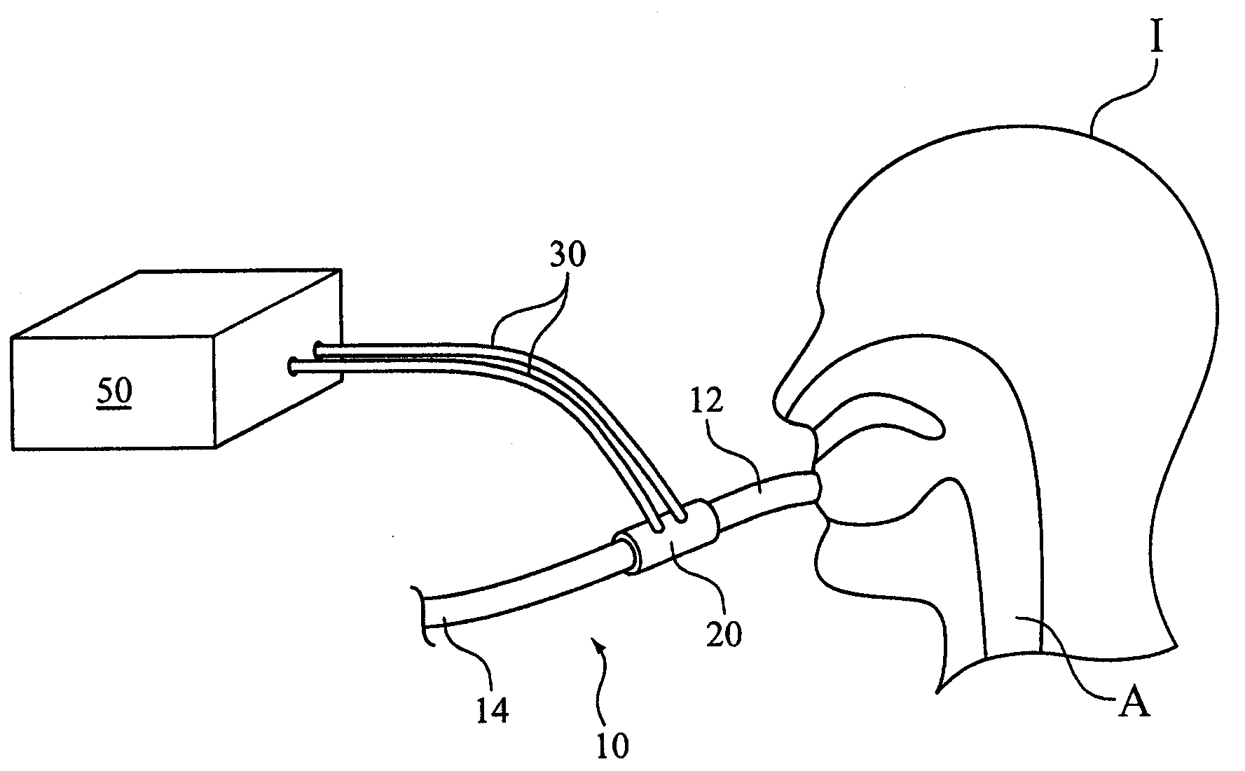
[0022]With reference to FIG. 1, a respiratory conduit 10 is depicted. In an exemplary embodiment of the present invention, respiratory conduit 10 is a breathing circuit (also referred to as a patient circuit) that includes a patient interface at one end 12.

[0023]The patient interface is any device, invasive or non-invasive, that is adapted to coupled the respiratory conduit in fluid communication with an airway A of an individual I, such as an endotracheal tube, tracheal tube, nasal mask, nasal / oral mask, or a nasal cannula. As depicted, one end 12 of respiratory conduit 10 is placed in communication with airway A, while another end 14 of the respiratory conduit opens to a source of gas to be inhaled by individual I. The present invention contemplates that the source or gas can be any gas source, such as atmosphere, an oxygen supply, a ventilator, a pressure support system (e.g., CPAP, bi-level pressure support system, auto-titration pressure support system), a source of other gas (...


PUM


Abstract

An electro-pneumatic assembly for use in a respiratory measurement system that includes a housing having a plurality of channels defined therein and a plurality of walls forming a cavity. The housing includes an upper face, a lower face, and a plurality of apertures defined in the lower face of the housing to. A cover is affixed to the upper face of the housing to enclose the cavity thereby forming a chamber, and to enclose the channels thereby forming a plurality of conduits. A control component is operatively coupled to at least one aperture in the plurality of apertures, and a measurement component is operatively coupled to at least one aperture in the plurality of apertures. This assembly provides a simple, robust component for managing the pneumatics of the respiratory measurement system.

Description

CROSS-REFERENCE TO RELATED APPLICATIONS[0001]This application claims priority under 35 U.S.C. § 119(e) from provisional U.S. patent application No. 60 / 968,732, filed Aug. 29, 2007, the contents of which are incorporated herein by reference.BACKGROUND OF THE INVENTION[0002]1. Field of the Invention[0003]The present invention pertains to an integrated electro-pneumatic assembly for use in a respiratory measurement system and a method of assembling same.[0004]2. Description of the Related Art[0005]Respiratory flow and pressure measurements during the administration of anesthesia, in intensive care environments, and in monitoring the physical condition of athletes and other individuals prior to and during the course of training programs and other medical tests provides valuable information for assessing cardiopulmonary function and breathing circuit integrity. Many different technologies have been applied to create flow and / or pressure sensors that attempt to meet the demanding requirem...

Claims


Application Information

Patent Timeline
Patent Type & Authority Applications(United States)
IPC IPC(8): A61B5/08
CPCA61B5/087A61B2562/0247A61B5/0876
Inventor SCAMPOLI, DAVE
Owner RIC INVESTMENTS LLC
Why Eureka
Try Eureka