Mold Insert Fixture Mechanism

a technology of mold inserts and fixture mechanisms, applied in the field of mold insert retaining structure, can solve the problems of time-consuming and labor-intensive activity

Inactive Publication Date: 2009-03-05
HUSKY INJECTION MOLDING SYST LTD
View PDF16 Cites 23 Cited by
  • Summary
  • Abstract
  • Description
  • Claims
  • Application Information

AI Technical Summary

Benefits of technology

[0014]In accordance with a first aspect of the present invention a mold insert retaining structure is provided for quick removal and replacement of a mold insert on a mold plate of an injection mold. The mold insert retaining structure includes a retainer plate connectable, in use, to a mold plate with a spring-clamp, a first bayonet structure defined on the retainer plate and a second bayonet structure associated with the mold insert, the first bayonet structure and the second bayonet structure configured to cooperate for providing, in use, a twistable interconnection therebetween, the first bayonet structure and the second bayonet structure may be arranged between a clamped position wherein the second bayonet structure is clamped between the first bayonet structure and the mold plate, and an unclamped position wherein the first bayonet structure is disengaged from the second bayonet structure.

Problems solved by technology

This is time consuming and labor intensive activity.

Method used


Image

  • Mold Insert Fixture Mechanism
  • Mold Insert Fixture Mechanism
  • Mold Insert Fixture Mechanism

Examples


Embodiment Construction

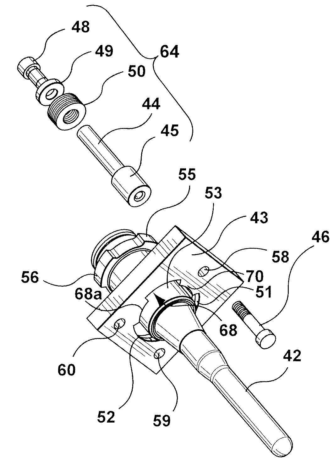
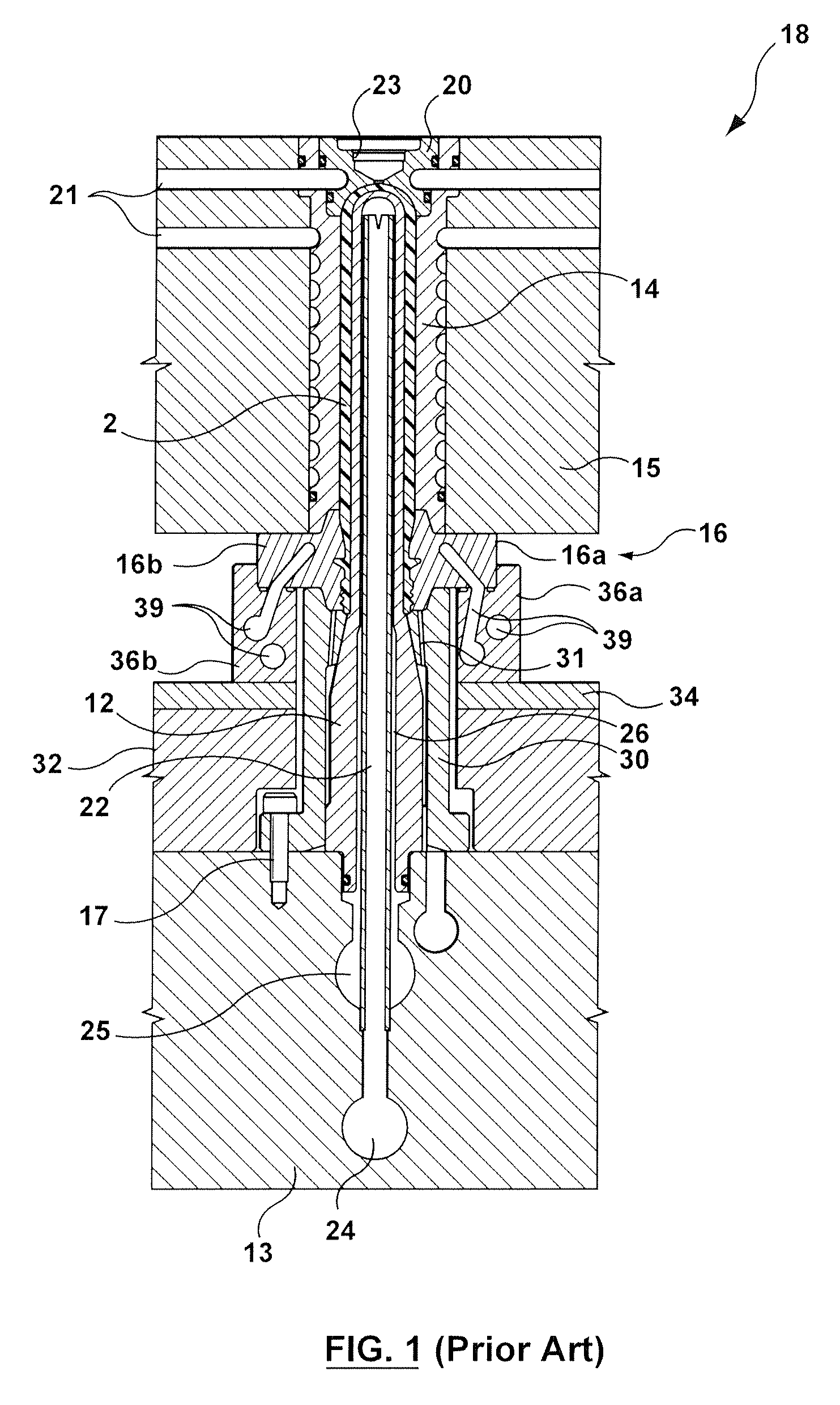
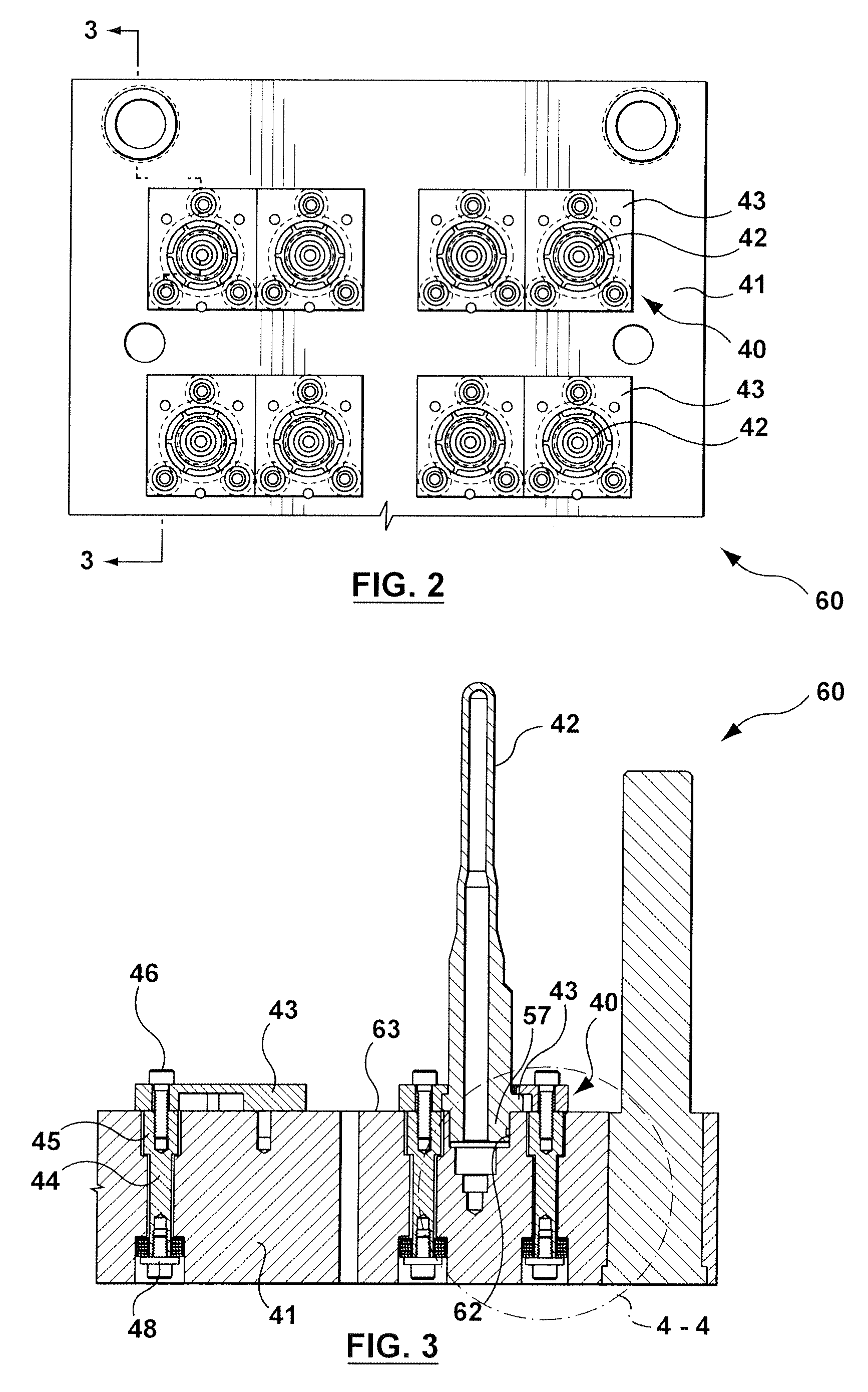
[0023]Referring to FIG. 2, a portion of a mold plate assembly 60 in accordance with a non-limiting embodiment of the present invention is shown. The mold plate assembly 60 may be used with the injection mold 18 described previously and shown with reference to FIG. 1. The portion of the mold plate assembly 60 includes a mold plate 41 with eight mold inserts 42 retained thereon by a corresponding plurality of mold insert retaining structures 40. Other configurations of the mold plate assembly are, of course, possible such as, for example, different quantities of the mold inserts 42 and corresponding mold insert retaining structures 40. Each of the mold insert retaining structures 40 is shown as including a retainer plate 43 holding a corresponding one of the mold inserts 42 to the mold plate 41. The retention of the mold inserts 42 on the mold plate 41 will be described in more detail hereinafter with reference to FIGS. 3, 4 and 5.

[0024]In the non-limiting embodiment the mold insert 4...


PUM

PropertyMeasurementUnit
diameteraaaaaaaaaa
timeaaaaaaaaaa
clamping pressureaaaaaaaaaa

Abstract

A mold insert retaining structure including a retainer plate connectable, in use, to a mold plate with a spring-clamp, a complementary bayonet structure defined on the retainer plate and a mold insert for providing a twistable interconnection therebetween, a portion of the mold insert clamped between the retainer plate and the mold plate.

Description

BACKGROUND OF INVENTION[0001]1. Field of the Invention[0002]The present invention relates, generally, to retaining a mold insert on a mold plate of an injection mold and more particularly, but not exclusively, the invention relates to a mold insert retaining structure having a spring-clamp for clamping the mold insert to the mold plate.[0003]2. Background Information[0004]The state of the art includes U.S. Pat. Nos. 4,911,632 issued Mar. 27, 1990 to Dana Corporation, 3,871,611 issued Mar. 18, 1975 to Phyllis Taketa, 4,556,377 issued Dec. 3, 1985 to Husky Injection Molding Systems Ltd., and 5,750,161 issued May 12, 1998 to Electra Form, Inc.[0005]U.S. Pat. No. 4,911,632 describes a structure for releasably securing a plurality of mold inserts to a mold plate attached to a power press machine. A mold insert is inserted within an aperture by aligning the tabs with the spaces between the protrusions and moving the mold insert axially therein. Then, by rotating the mold insert relative t...

Claims


Application Information

Patent Timeline
Patent Type & Authority Applications(United States)
IPC IPC(8): B29C45/36
CPCB29K2105/253B29C45/2675
Inventor FISCH, RALF WALTERKMOCH, SVEN
Owner HUSKY INJECTION MOLDING SYST LTD
Why Eureka
Try Eureka