
Wavelength tunable light source, control method and control program thereof, and optical module

Inactive Publication Date: 2009-03-05
NEC CORP
View PDF6 Cites 14 Cited by
  • Summary
  • Abstract
  • Description
  • Claims
  • Application Information

AI Technical Summary

Benefits of technology

[0015]It is therefore an exemplary object of the present invention to provide a wavelength tunable light source and the like, which can improve the detection accuracy of the optical powers without increasing the size of the device, etc., when controlling a plurality of light variable parts to minimize the sum of a plurality of optical powers.

Problems solved by technology

However, the wavelength tunable light sources disclosed in Patent Document 1 have following issues.
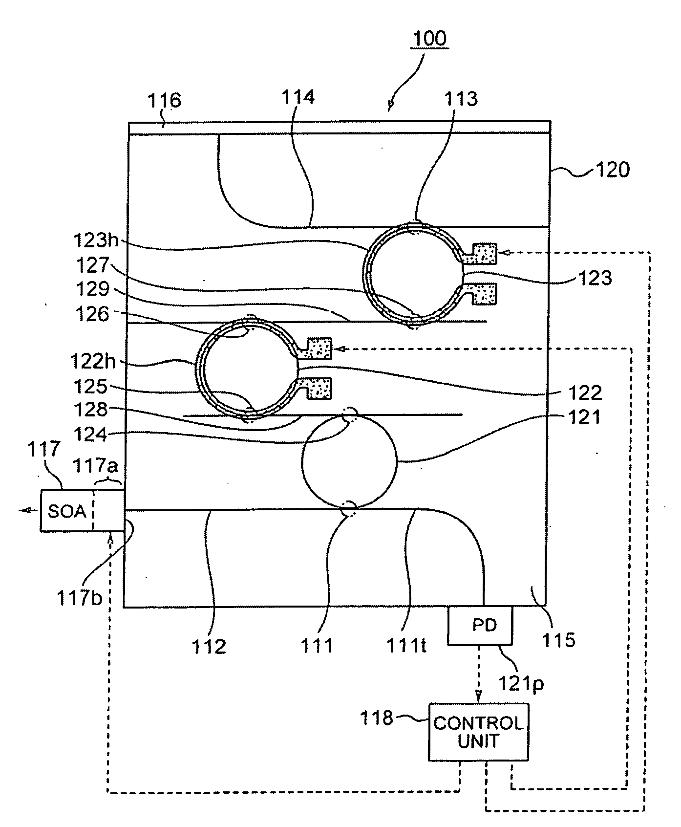
This generate variations in distribution of light on the light-receiving face of the light-receiving element 121p, thereby deteriorating the precision of the photocurrents.
Use of light-receiving elements having a larger light-receiving face for reducing the influences of such interference fringes generates other issues such as an increase in the size of the device and an increase in the price thereof.

Method used


Image

  • Wavelength tunable light source, control method and control program thereof, and optical module
  • Wavelength tunable light source, control method and control program thereof, and optical module
  • Wavelength tunable light source, control method and control program thereof, and optical module

Examples


Embodiment Construction

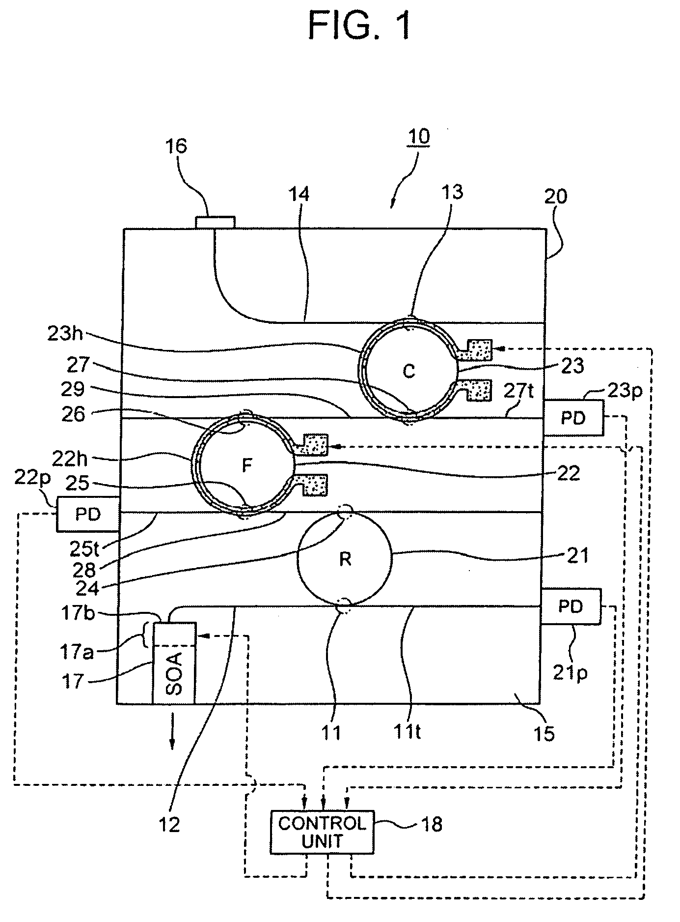
[0038]FIG. 1 is a plan view showing a first exemplary embodiment of a wavelength tunable light source according to the present invention (a part thereof is shown as a block diagram) Explanations will be provided hereinafter by referring to this drawing.

[0039]A wavelength tunable light source 10 according to this exemplary embodiment includes: a multiple ring resonator 20 including coupled ring resonators 21, 22, 23 which have different optical path lengths from each other; light-receiving elements 21p, 22p, 23p as photosensor parts for detecting optical powers outputted from the ring resonators 21, 22, 23 via through ports 11t, 25t, 27t; film-like heaters 22h, 23h as a plurality of light variable parts which individually work on the ring resonators 22 and 23 to change the transmittance of the multiple ring resonator 20; an SOA 17 as a light input / output part which supplies light to the multiple ring resonator 20 and emits the light returned from the multiple ring resonator 20 to the...


PUM


Abstract

To improve optical power detection accuracy without increasing size, etc. of a device, when controlling a plurality of light variable parts such that the sum of a plurality of optical powers becomes the minimum. Provided is a wavelength tunable light source for changing the wavelength of light by using a multiple resonator including two or more coupled resonators with different optical path lengths from each other. The light source includes: a single or more light variable part for changing transmittance of the resonators; photosensor parts which detect each light outputted from the two or more resonators by each of the resonators as optical powers being converted into electric power values; and a control unit which adds the optical powers detected by the photosensor parts by each resonator, and controls changes in the transmittance by the light variable parts such that the sum of the added optical powers becomes the minimum.

Description

CROSS-REFERENCE TO RELATED APPLICATION[0001]This application is based upon and claims the benefit of priority from Japanese patent application No. 2007-230593, filed on Sep. 5, 2007, the disclosure of which is incorporated herein in its entirety by reference.BACKGROUND OF THE INVENTION[0002]1. Field of the Invention[0003]The present invention relates to a wavelength tunable light source and the like capable of changing wavelengths of light by using a multiple resonator, which can be used for a transmission system and the like such as WDM (Wavelength Division Multiplexing).[0004]2. Description of the Related Art[0005]FIG. 16 is a plan view showing a wavelength tunable light source disclosed in Patent Document 1 (Japanese Unexamined Patent Publication 2006-245346 (FIG. 1, FIG. 6, FIG. 13, etc.): a part thereof is illustrated as a block diagram). FIG. 17 is a graph showing a control method for changing the wavelength of the wavelength tunable light source that is shown in FIG. 16. Expl...

Claims


Application Information

Patent Timeline
IPC IPC(8): H01S3/10H01S3/04
CPCH01S5/02216H01S5/02248H01S5/02284H01S5/142H01S5/06804H01S5/1032H01S5/0612H01S5/02325H01S5/02251
Inventor SUZUKI, KOUICHI
Owner NEC CORP
Learn More