
System and method for transmitting and activating a plurality of control data

Inactive Publication Date: 2009-02-26
BIOTRONIK SE & CO KG
View PDF4 Cites 7 Cited by
  • Summary
  • Abstract
  • Description
  • Claims
  • Application Information

AI Technical Summary

Benefits of technology

[0019]The invention is based on the insight that in the event of a plurality of associated control data, the use of this control data may only be performed reliably if it is ensured in a suitable manner that all control data are also completely provided. The implant may execute the changes at one stroke if and only if an entire packet has been received. It is important for the safety and reliability of the implementation of the control data that either all changes are executed together, or none at all.
[0021]In one version of the invention, the medical device is an implantable cardiac pacemaker or defibrillator-cardioverter. Secure communication of programming data or firmware updates according to the invention is advantageous particularly during operation of a cardiac pacemaker or a defibrillator-cardioverter.
[0025]In one version of the invention, the control data include meta-control data for the control unit for using the control data during the control of functions of the medical device, in particular information in regard to a sequence, a chronological succession, and / or a duration of the use of the control data and / or information in regard to a condition for the use of the control data. In addition to the actual control data, information on the use of the control data is contained in the control data set, which allows greater flexibility of the system according to the invention and better response to operator wishes.
[0032]In one version of the invention, the control data set end signal and the control data set start signal are each provided with an identifier, which allows an assignment of control data set start signal and control data set end signal to one another. An identification of the start and end signals is used for identification and allows, inter alia, different control data sets to be transmitted in parallel without the end and start signals being confused with one another.

Problems solved by technology

During a long transmission, an interruption of the transmission by a loss of connection can occur.
In addition, during such a transmission, a chronological or logical assignment between different items of data may be lost.
The control data thus arrive incomplete or corrupted at the implant, which may result in a malfunction of the implant upon an implementation / execution of the control data (e.g., acceptance of the operating parameters or overriding of the firmware).
When firmware is updated via remote programming, the problem additionally results that many reprogrammings must be executed, with only one containing the new implant control software.

Method used


Image

  • System and method for transmitting and activating a plurality of control data
  • System and method for transmitting and activating a plurality of control data
  • System and method for transmitting and activating a plurality of control data

Examples


Embodiment Construction

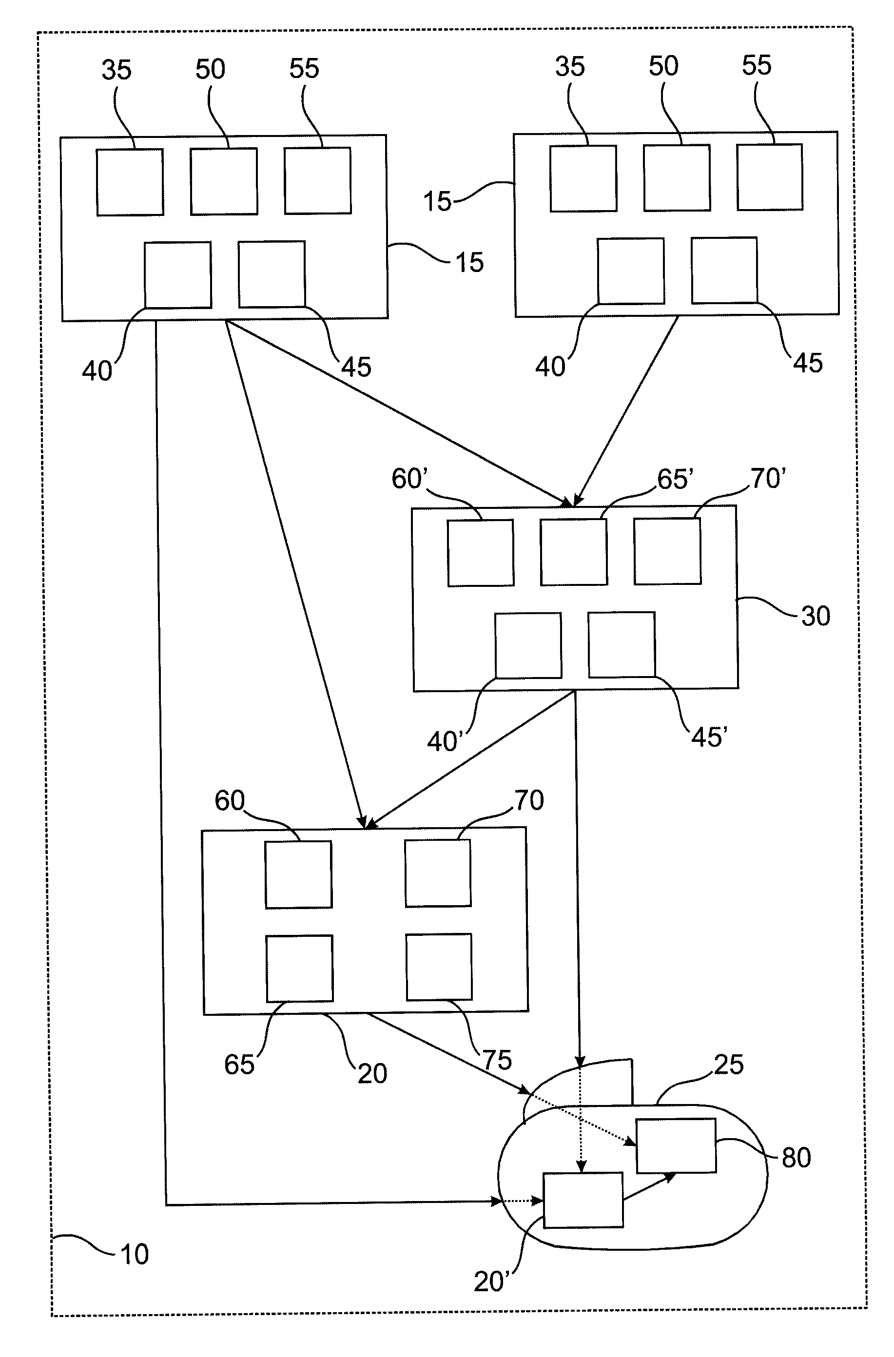
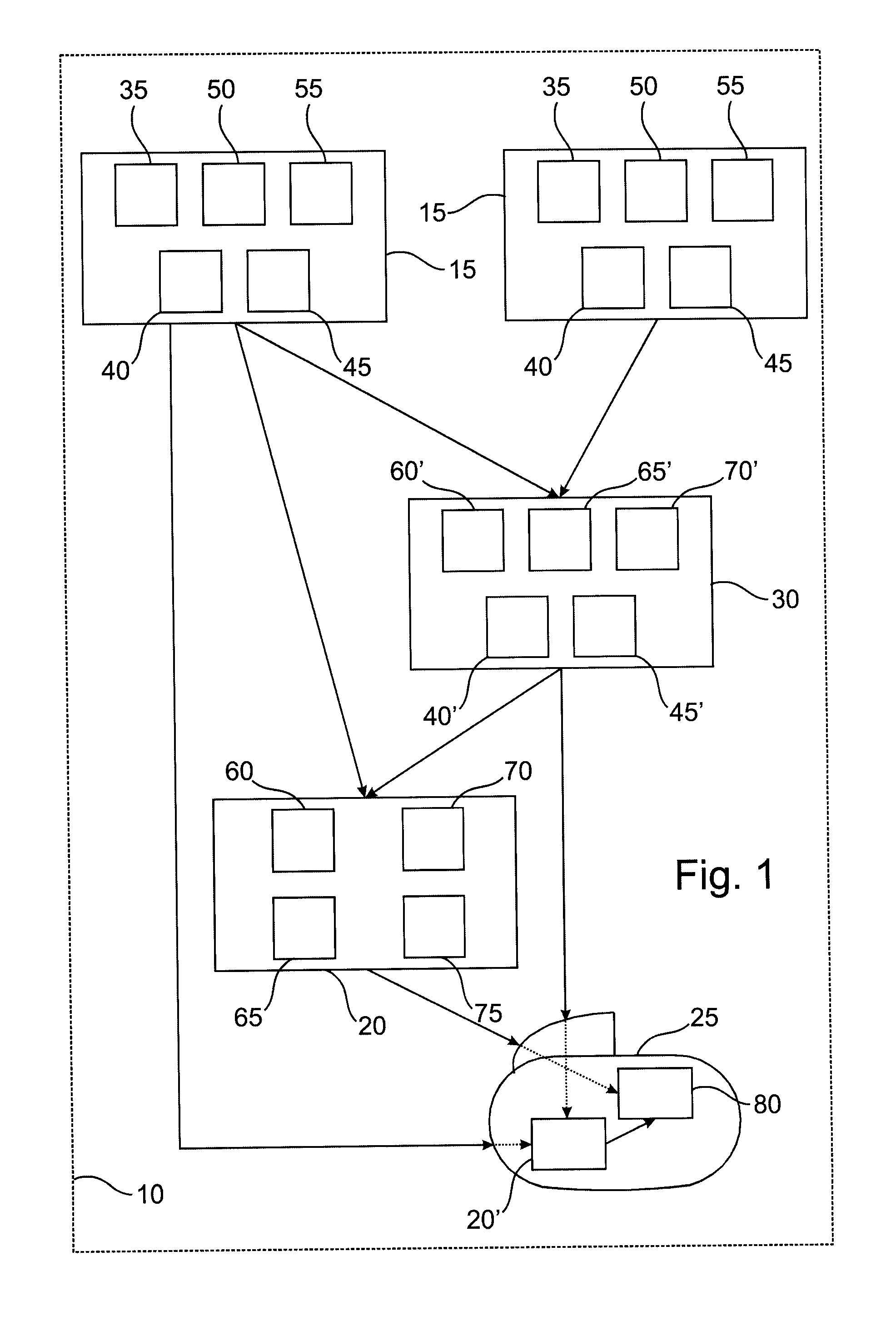
[0043]FIG. 1 shows a schematic illustration of an exemplary version of the invention. The system 10 includes a first and a second source unit 15, a collection unit 20, an implant 25, and a combination unit 30.

[0044]The first and the second source unit 15 are constructed essentially identically, operate corresponding to one another, and each include a data set unit 35, a check data unit 40, a transmitting unit 45, a programming device 50, and a server 55. The collection unit 20 includes a receiving unit 60, a storage unit 65, a check unit 70, and a transmitting unit 75. The implant 25 includes a programmable control unit 80 and a separate collection unit 20′, which is constructed and operates fundamentally like the foregoing collection unit 20. The combination unit 30 includes a receiving unit 60′ similar to the receiving unit 60 of the collection unit 20, a storage unit 65′ similar to the storage unit 65 of the collection unit 20, a check unit 70′ similar to the check unit 70 of the...


PUM


Abstract

A cardiac pacemaker, defibrillator, or other programmable medical device (25) includes a source unit (15) and a collection unit (20). The source unit (15) has a check data unit (40) generating at least one check datum for control data for the medical device (25), and a transmitting unit (45) transmitting the control data and the check datum to the collection unit (20). The collection unit (20) has a storage unit (65) storing the control data, a check unit (70) checking the integrity of the control data using the check datum, and a transmitting unit (75) transmitting the control data to a programmable control unit (80) of the medical device (25) only if the integrity of the control data is established by the check unit (70). The control unit (80) of the medical device (25) controls the functions of the medical device (20) on the basis of the transmitted control data.

Description

FIELD OF THE INVENTION[0001]The present invention relates to a system and a method for transmitting and activating a control data for a programmable personal medical device, in particular for an implantable medical device such as a cardiac pacemaker, defibrillator, or the like. In addition, the present invention relates to such a medical device and a source unit for control data.BACKGROUND OF THE INVENTION[0002]A medical device such as a cardiac pacemaker typically receives new control data several times during its operation, with the control data including matters such as changes to the operating parameters of the cardiac pacemaker, software or firmware updates or commands for the cardiac pacemaker, etc. When programming an implant such as a cardiac pacemaker, a programming session may involve the alteration of some parameters and the issuance of associated commands to the implant, such as a request to restart statistics or to begin detection of patient data, and the transmission o...

Claims


Application Information

Patent Timeline
IPC IPC(8): A61N1/39A61N1/08A61N1/362
CPCA61N1/37235A61N1/37282A61N1/3727A61N1/37264Y10S128/92Y10S128/923
Inventor SEVERIN, THOMASBUNGARTZ, JOERN
Owner BIOTRONIK SE & CO KG
Learn More