
Apex Locator For Endodontic Procedures

a technology of endodontic procedures and locators, applied in the field of apex locators for endodontic procedures, can solve problems such as under-reported siz

Inactive Publication Date: 2009-02-26
BUCHANAN L STEPHEN
View PDF6 Cites 4 Cited by
  • Summary
  • Abstract
  • Description
  • Claims
  • Application Information

AI Technical Summary

Benefits of technology

[0009]Besides the described units being smaller, the small size allows the clinician to place the display device in a readily visible location right next to the patient's head. The design, with a single multi-use attachment, allows dentists to place the miniaturized device on the dentist's wrist, clipped to the patient bib, attached magnetically to another device in the operatory such as a microscope or x-ray view box, or even, with the fold out stand deployed, on the countertop if necessary.
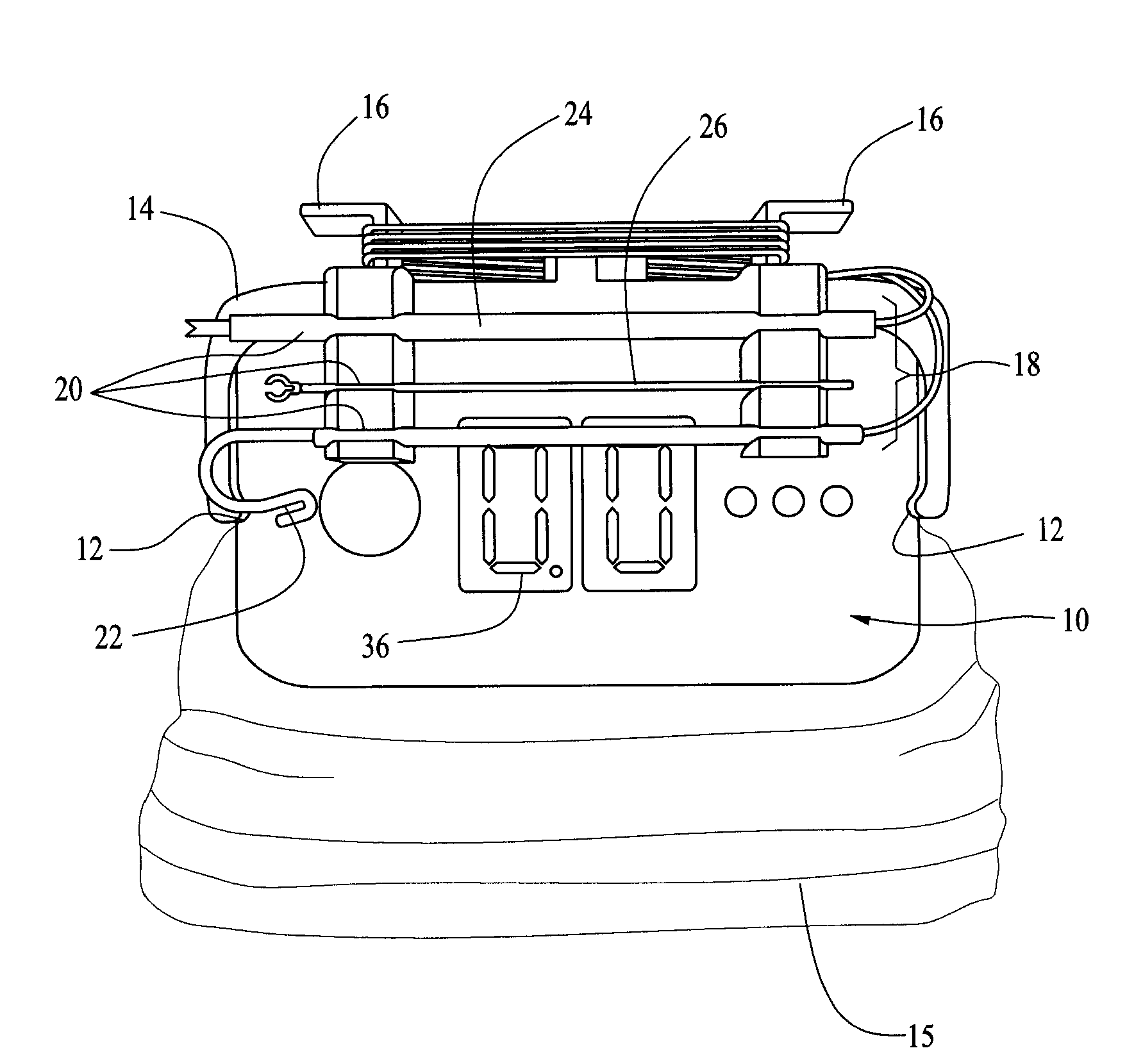
[0010]Furthermore, this detachable device has a cord caddy around which the two leads are wrapped and a clip to secure each of the lead tips. This detachable device is easily placed in an autoclave bag for sterilization, and clips over the apex locator control device allowing placement of a zip-lock bag around the device to act as a barrier to bacterial contaminants. Furthermore, this cord management system allows the plugs on the lead set to become automatically attach when it is clipped onto the apex locator and automatically become unplugged when the caddy is removed for sterilization.

Problems solved by technology

Most of the existing apex locator devices have large graphical displays that are visually attractive but unnecessary in achieving the objective of locating the end point of the canal.
Size is an underappreciated issue in the dental environment.

Method used


Image

  • Apex Locator For Endodontic Procedures
  • Apex Locator For Endodontic Procedures
  • Apex Locator For Endodontic Procedures

Examples


Embodiment Construction

[0017]An electronic apex locator and root length measuring device comprises a display component or unit 10 and a detachable lead caddy 14 carrying electrical leads for use in locating the apex and measuring the root length.

[0018]The apex locator display unit 10 is miniaturized to approximately 1″ deep, by 2.5″ wide, by 1.5″ high, having indentations 12 on either side for engagement of the cord caddy stand 14 which is clipped onto the display unit 10 after the display unit is enclosed in a clear plastic zip-lock barrier bag 15. The plug 19 from the lead set is held in a downward position so that it automatically penetrates the plastic barrier bag 15 and is received into a lead connector 17 on the top of display unit 10 as it is secured over the barrier bag 15. Assembly does not compromise the sterility of either the bagged display or the leads on the caddy.

[0019]The caddy stand 14, has cord winding posts 16 on its top surface to hold the lead set 18 and clips 20 on its front surface ...


PUM


Abstract

An electronic device for locating the apex of a root canal within a tooth of a dental patient has a display screen on a display component to provide an image indicating when the apex of a root canal has been located. A free end of a first electrical lead is provided for placement within the root canal or in contact with an electrically conductive tool within the root canal. A free end of a second electrical lead is used to establishing a ground on a conductive portion of the dental patient such as a tissue surface within the mouth. The opposite ends of each of the leads is connected to the display component. Removeably attached to the display component is a lead carrier. The detachable lead carrier and the leads mounted thereon can be sterilized as a unit and then attached to the display component, which is bagged in a sterile barrier, for performing the apex locating procedure. The apex locator has one or more mounting structures for placing the display in a location adjacent the patients head, attached to adjacent instrumentation, or attached to the dental practitioner's hand or arm such that the display image is readily visible by the dental practitioner during the apex locating procedure.

Description

BACKGROUND[0001]This application claims the benefit of U.S. Provisional Application No. 60 / 957,092 filed Aug. 21, 2007.[0002]Endodontics, a specialty of the field of dentistry, relates to the diagnosis and treatment of diseases of the dental pulp tissues residing in teeth. When pulp in a tooth becomes diseased and must be treated to retain that tooth in the patient's mouth, it is necessary to enter the pulp chamber, locate each of the canals contained in the tooth's root structure, and to pass endodontic instruments, called files, through each canal to it's end point, the apical foramen (the apex). During this initial negotiation of the canal spaces and during the procedures that follow, which include the shaping, cleaning, and filling of those canals it is critical to determine the exact endpoint of these spaces so that none of the infected canal space is left untreated or that surplus filling materials are not pushed through the ends of the root canal, both outcomes being risks fo...

Claims


Application Information

Patent Timeline
IPC IPC(8): A61C3/00
CPCA61C19/042A61C19/041
Inventor BUCHANAN, L. STEPHEN
Owner BUCHANAN L STEPHEN
Learn More