Pulse radar, car radar and landing assistance radar

a technology of pulse radar and pulse beam, which is applied in the direction of reradiation, measurement devices, instruments, etc., can solve the problems of increasing the cost of a circuit, reducing the number of channels which can be set in a single frequency band, and difficulty in antenna design, so as to reduce transmission power and reduce the amount of attenuation , the effect of reducing the occupied band width

Inactive Publication Date: 2009-02-26
SUBARU CORP
View PDF3 Cites 64 Cited by
  • Summary
  • Abstract
  • Description
  • Claims
  • Application Information

AI Technical Summary

Benefits of technology

[0025]In general, the lower the frequency of a wave, the smaller the amount of attenuation causes. The carrier wave of the radar of the present invention can be lowered to a relatively-low frequency, and hence transmission power can be lowered to a relatively-low level.
[0026]Moreover, the occupied band width can be made relatively narrower. Therefore, a band of a UWB radar of the present invention can be assigned at a vacant band between frequency bands assigned to other systems, such as a WiMAX, thereby avoiding occurrence of radio interference.

Problems solved by technology

Broadening of the occupied bandwidth raises various problems, such as a necessity for a high frequency for a carrier wave, difficulty in designing of an antenna, and an increase in cost of a circuit, as well as a decrease in the number of channels which can be set in a single frequency band.

Method used


Image

  • Pulse radar, car radar and landing assistance radar
  • Pulse radar, car radar and landing assistance radar
  • Pulse radar, car radar and landing assistance radar

Examples


first embodiment

OF THE PRESENT INVENTION

[0061]FIGS. 6 through 8 are block diagram of a system of a first embodiment of the invention. In the first embodiment, a radar having high short-range resolution in a narrow band is applied to a short-range radar intended for use with an automobile drive assist system, and a frequency band and a high-frequency circuit are shared with a keyless entry system. The keyless entry system is used to open and close doors of a parked car which an engine is inoperative. The short-range radar intended for use with a drive assist system is used while the engine is in operation. Since simultaneous use of both the keyless entry and the short-range radar during ordinary operation is impossible, shared use of the frequency band and the high-frequency circuit poses no problems. Moreover, a wavelength in a frequency band of 300 [MHz] used for the keyless entry usually assumes a value of about 1 m. Hence, the wavelength is becomes equal to the width of a vehicle body in terms o...

second embodiment

OF THE PRESENT INVENTION

[0087]FIGS. 14 through 16 are block diagrams of a system of a second embodiment of the present invention. In the present embodiment, a radar of the present embodiment having high short-range resolution in a narrow band is used as a landing assist radar intended for assisting landing operation of a helicopter or the like. When compared with a radar intended for use with an automobile driving assist system, the landing assist radar requires a comparatively-long range, and hence a UWB (Ultra Wide Band) is used.

[0088]A nonlinear effect in a UWB multiplier is not negligible, and hence a neural network capable of addressing a nonlinear effect is added to a feedback line from the transmission circuit as means for eliminating a transmission waveform interfering with an answering waveform from a received waveform. Moreover, a phase change detector 610 for extracting a rapid phase delay is added as means for detecting arrival or completion of an answering wave. A time ...


PUM


Abstract

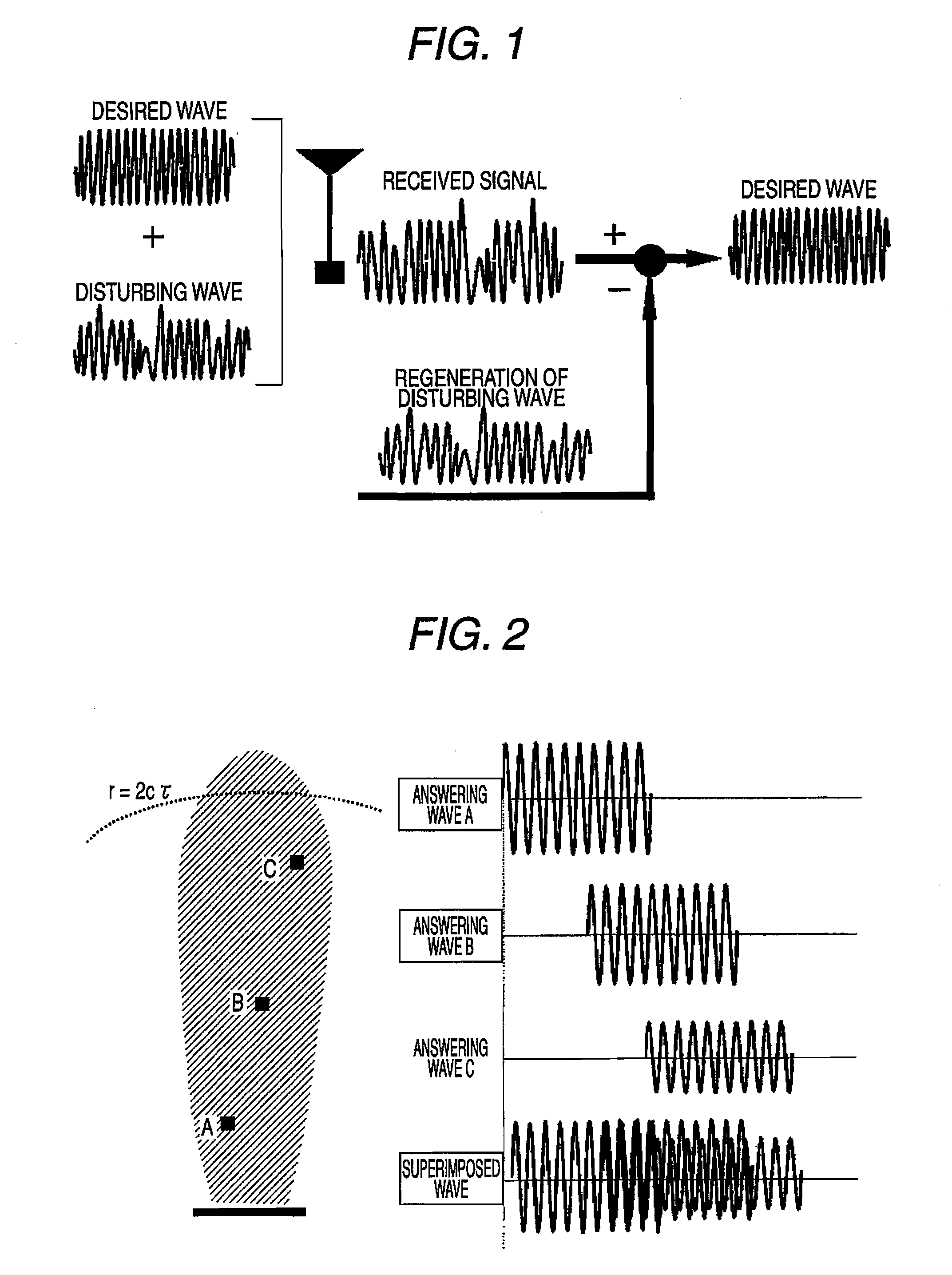
A pulse radar is provided with a filter for eliminating a transmission waveform interfered with an answering signal from a received waveform, and a harmonic detector or a phase delay detector for detecting arrival and end of the answering signal reflected on a target.

Description

CROSS-REFERENCE TO RELATED APPLICATION[0001]The disclosure of Japanese Patent Application No. 2006-347888 filed on Dec. 25, 2006 including the specification, drawings and abstract is incorporated herein by reference in its entirety.BACKGROUND OF INVENTION[0002]1. Field of the Invention[0003]The present invention relates to a pulse radar based on the principle that a distance is computed from a time difference from when a pulse signal is reflected from a target until when the reflected pulse signal is received. Particularly, a pulse radar is mounted on an automobile and on an aircraft which flies horizontally at a very low altitude.[0004]2. Description of the Related Art[0005]The following three systems have hitherto been used for a radar and a radio sensor, as disclosed in “New Millimeter Wave Technique” pg. 278 (Tasuku TESHIROGI / Tsutomu YONEYAMA, Ohmsha Co., Nov. 25, 1999)[0006](1) Pulse Radar[0007](2) FM-CW Radar (Frequency Modulation Continuous Wave Radar[0008](3) Two-tone CW (Co...

Claims


Application Information

Patent Timeline
Patent Type & Authority Applications(United States)
IPC IPC(8): G01S13/08G01S13/00
CPCG01S13/10G01S7/285
Inventor HATONO, ATSUO
Owner SUBARU CORP
Why Eureka
Try Eureka