Injection system having a device for metering fuel into an exhaust system of an internal combustion engine and a method for this purpose

a fuel injection system and fuel technology, applied in liquid fuel feeders, machines/engines, mechanical equipment, etc., can solve the problems of unsuitable combustion engines for ensuring effective regeneration of particle filters, adversely affecting the thermodynamic efficiency of internal combustion engines, etc., to achieve advantageously smooth fuel pressure fluctuations, improve the accuracy of fuel pressure control upstream of the metering valve, and improve the effect of accuracy

Inactive Publication Date: 2009-02-26
DAIMLER AG
View PDF7 Cites 14 Cited by
  • Summary
  • Abstract
  • Description
  • Claims
  • Application Information

AI Technical Summary

Benefits of technology

The invention relates to a device for injecting fuel into the exhaust system of a diesel engine. The device includes a high-pressure pump, an accumulator, injectors, a control valve, a metering valve, and a pressure regulating valve. The device is controlled by a fuel metering unit that includes a fuel control valve and a metering valve. The pressure regulating valve keeps the pressure of the fuel upstream of the metering valve at a certain level, ensuring accurate injection of fuel into the exhaust system. The device can be controlled by a throttle and a control valve, and the fuel spray nozzle can be positioned in the exhaust system. The device can be connected to the injection system and the exhaust system in a space-saving manner. The invention also includes a method for controlling the injection of fuel into the exhaust system. The technical effects of the invention include improved accuracy in fuel injection, improved control of fuel pressure, and improved regeneration of particle filters in the exhaust system.

Problems solved by technology

A disadvantage here is that the spraying of fuel by means of the injectors adversely affects the thermodynamic efficiency of the internal combustion engine and the device for metering fuel into the exhaust system of the internal combustion engine is not suitable for ensuring effective regeneration of the particle filter at low exhaust-gas and oxidation catalytic converter or particle filter temperatures.

Method used


Image

  • Injection system having a device for metering fuel into an exhaust system of an internal combustion engine and a method for this purpose
  • Injection system having a device for metering fuel into an exhaust system of an internal combustion engine and a method for this purpose
  • Injection system having a device for metering fuel into an exhaust system of an internal combustion engine and a method for this purpose

Examples


Embodiment Construction

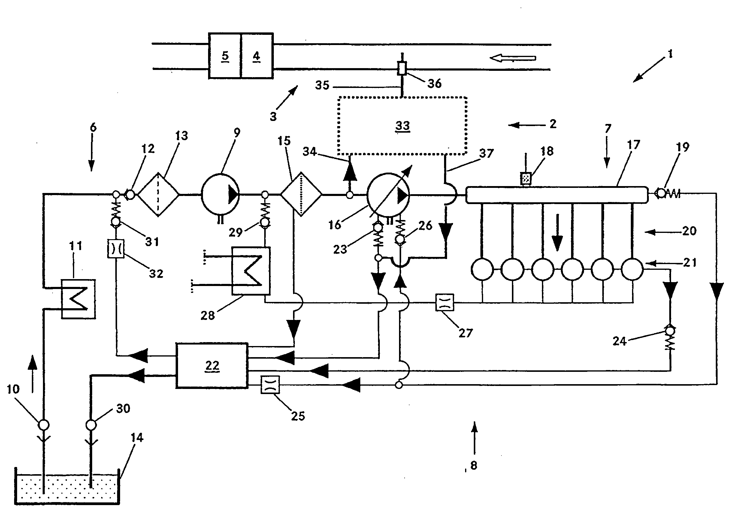
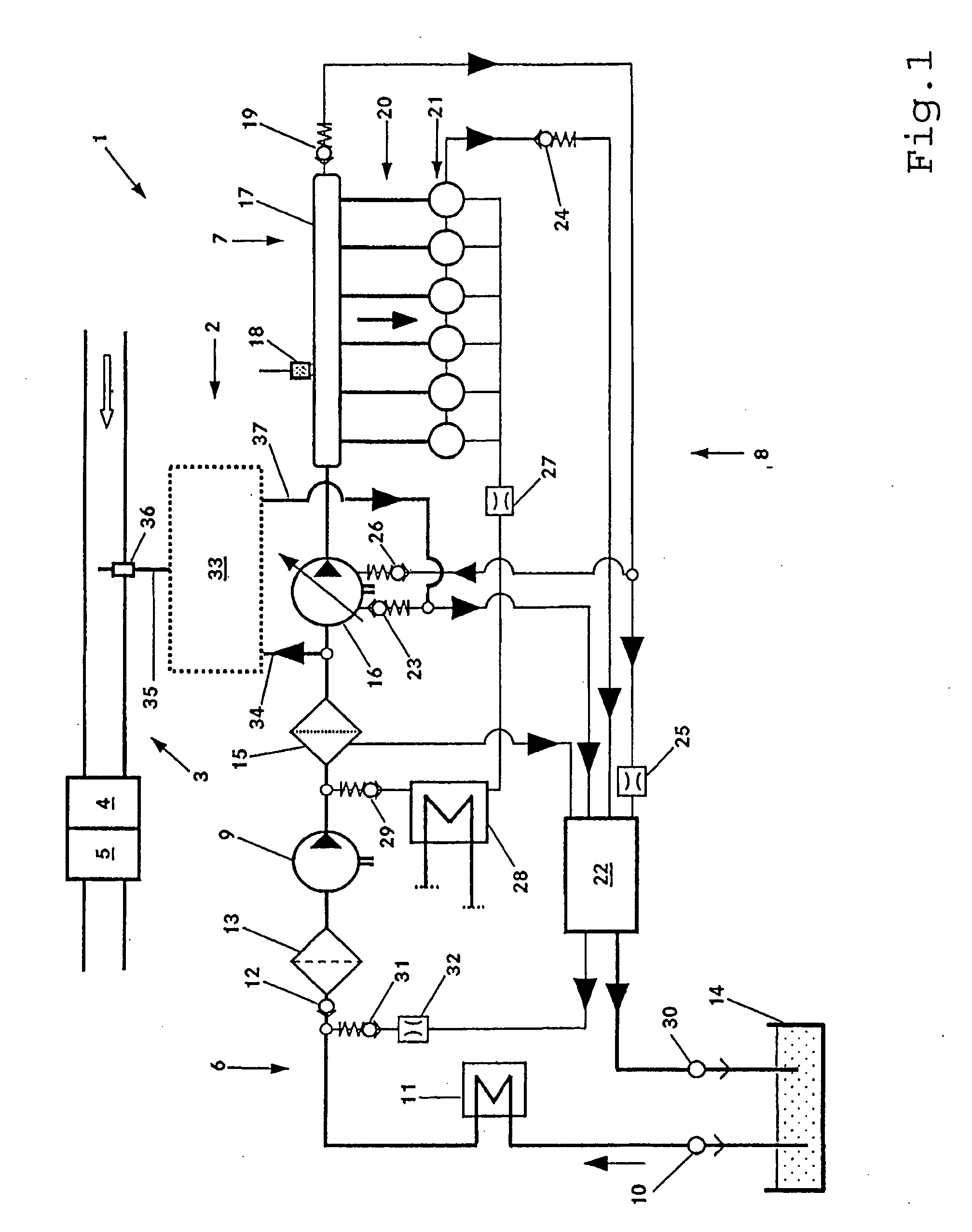
[0023]As shown in FIG. 1 a fuel injection system 1 for a diesel engine includes a device 2 for metering fuel into an exhaust system 3 of an internal combustion engine.

[0024]The fuel injection system 1 for injecting fuel into the cylinders of the internal combustion engine in particular a diesel internal combustion engine, includes an accumulator (common rail). The injection system 1 however also supplies fuel to the device 2 for metering fuel into the exhaust system 3 of the internal combustion engine (not illustrated in any more detail). Provided in the exhaust system 3 is an exhaust-gas purification system having an oxidation catalytic converter 4 and a particle filter 5 which is arranged downstream of the oxidation catalytic converter 4. The device 2 for metering fuel discharges fuel into the exhaust system 3 upstream of the oxidation catalytic converter 4. The fuel is mixed with the exhaust gas and is carried with the exhaust gas to the oxidation catalytic converter 4. In the ox...


PUM


Abstract

In an injection system having a device for metering fuel into an exhaust system of a Diesel engine, and a method for controlling the injection of fuel into the exhaust system, wherein the injection system has a high-pressure pump which feeds fuel to an accumulator under high pressure and injectors which inject fuel from the accumulator into the combustion chambers of the internal combustion engine, a fuel spray nozzle arranged in the exhaust system is in communication with the injection system via a fuel metering unit including a control valve and a metering valve and a pressure regulating valve is arranged between the control valve and the metering valve for controlling the pressure of the fuel being metered by the metering valve for injection into the exhaust system via the spray nozzle.

Description

[0001]This is a Continuation-in-Part Application of pending international patent application PCT / EP2007 / 001064 filed Feb. 8, 2007 and claiming the priority of German patent application 10 2006 099.3 filed Feb. 28, 2006.BACKGROUND OF THE INVENTION[0002]The invention relates to a fuel injection system including a device for metering fuel into an exhaust system of an internal combustion engine, particularly a common rail Diesel engine, with a high pressure fuel line extending from the common rail to the exhaust system for injecting fuel into the exhaust system and to a method for metering the fuel into the exhaust system.[0003]It is known to collect soot particles contained in the exhaust gas of diesel internal combustion engines in particle filters. To regenerate the particle filter, the soot which is trapped in the particle filter is oxidized by means of oxygen. The temperature of the particle filter required for oxidation can be attained with the aid of an oxidation catalytic conver...

Claims


Application Information

Patent Timeline
Patent Type & Authority Applications(United States)
IPC IPC(8): F02M63/00
CPCF01N3/0253F02M63/025F01N2610/1446F01N2610/03
Inventor HOFFMANN, MICHAELPICHLER, HELMUT
Owner DAIMLER AG
Why Eureka
Try Eureka