Construction module arrangement

a construction module and arrangement technology, applied in the field of construction art, can solve the problems of insufficient rigidity or strength for the purpose for which the construction module was intended, distortion of the panel, and many of the prior art modules were not visually attractive from all aspects, and achieve the effect of light weight, strong and rigidity

Active Publication Date: 2009-02-26
CORONADO HECTOR
View PDF7 Cites 0 Cited by
  • Summary
  • Abstract
  • Description
  • Claims
  • Application Information

AI Technical Summary

Benefits of technology

[0008]It is another object of the present invention to provide an improved construction module that is light in weight, strong and rigid.
[0009]It is another object of the present invention to provide an improved construction module that is economic to fabricate and economic for purchase by the end user.
[0010]It is yet another object of the present invention to provide an improved construction module that can be provided with a visually attractive appearance on all surfaces thereof.
[0011]It is yet another object of the present invention to provide an economical method of fabricating a light weight, rigid, strong and visually attractive construction module.

Problems solved by technology

While many of these modules were light weight, they often were not rigid enough or strong enough for the purpose for which they were intended.
Such lack of rigidity or strength often caused distortion of the panel when used for the intended purpose.
Also, many of these prior art modules were not visually attractive from all aspects from which they were viewed.
For example, even though a decorative cover could be placed on the exterior and / or interior surfaces of such structures such as doors, drawer fronts, cabinet walls and the like which are often viewed from both sides, the edge portions thereof were not as attractive as often desired.
Also, many of the prior art construction modules were relatively expensive to the end user, thereby limiting the use thereof.

Method used


Image

  • Construction module arrangement
  • Construction module arrangement
  • Construction module arrangement

Examples


Embodiment Construction

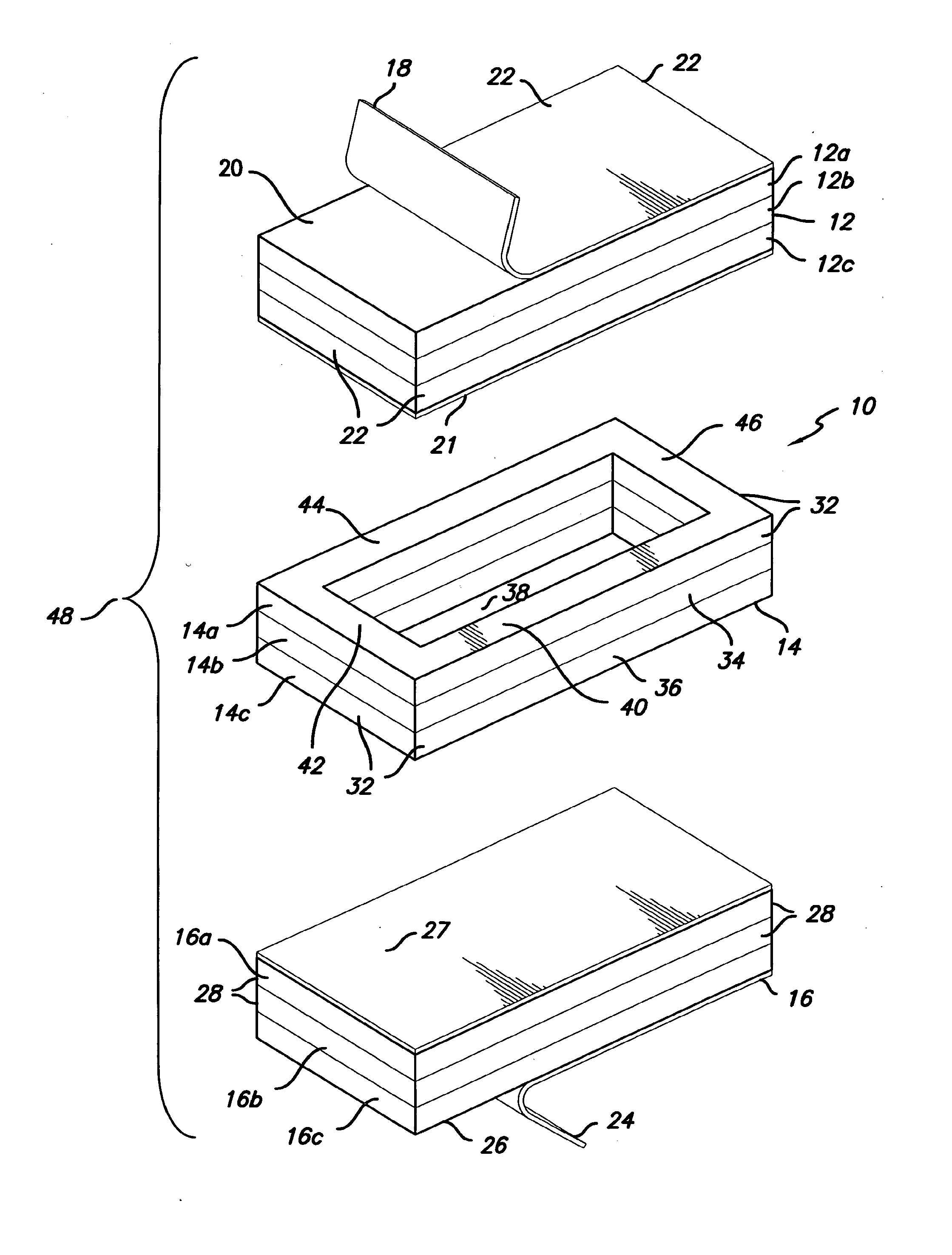
[0025]Referring now to the drawing, there is illustrated in FIG. 1 a first preferred embodiment of the present invention generally designated 10. The embodiment 10 has a top panel 12, an intermediate panel 14 and a bottom panel 16. The top panel 12 is comprised of a first plurality of thin sheet laminate layers 12a, 12b and 12c bonded together by a suitable adhesive therebetween. Each of the thin sheet laminate layers may be a wood sheet and each may have a thickness on the order of one eighth of an inch. All of the first plurality of thin sheet laminate layers 12a, 12b and 12c are substantially coextensive. It is to be understood that the thickness of each of the first plurality of thin sheet laminate layers 12a, 12b and 12c may be selected as desired for particular applications and, additionally, may not all be the same thickness. Further, the number of the first plurality of thin sheet laminate layers may be greater than three or less than three as desired for particular applicat...


PUM

PropertyMeasurementUnit
transparentaaaaaaaaaa
heat reactiveaaaaaaaaaa
weightaaaaaaaaaa

Abstract

A construction module having a multi-layered top panel, a multi-layered intermediate panel and a multi-layered bottom panel which are bonded together and desired cavities are provided through one or more of the top panel, intermediate panel and bottom panel.

Description

BACKGROUND OF THE INVENTION[0001]1. Field of the Invention[0002]This invention relates to the construction art and more particularly to an improved construction module and the method of making the improved construction module.[0003]2. Description of the Prior Art[0004]Construction modules have long been utilized in a variety of applications such as for walls, doors, cabinets, drawer fronts, counter tops and the like. In some applications, such as aircraft, recreational vehicles and similar structures, it is desired that the modules be as light weight as possible and still strong and rigid enough to be suitable for the intended purpose. Further, such modules are often required to be visually attractive so as to provide an appealing combination with the other decor in the structure. Additionally, it is, of course, desired that the construction module be economical to purchase by the end user and therefore be economical to fabricate so that the lower cost is passed on to the customer.[...

Claims


Application Information

Patent Timeline
Patent Type & Authority Applications(United States)
IPC IPC(8): E04C2/00E04B1/00B32B3/10E04D13/18E06B3/70
CPCE06B2003/7086B32B3/10B32B2419/00B32B2307/558B32B3/266B32B21/042B32B37/1207B32B21/14B32B2451/00B32B2307/718B32B7/12
Inventor CORONADO, HECTOR
Owner CORONADO HECTOR
Why Eureka
Try Eureka