
Rotatable illumination device on hand tools

a technology of rotating illumination and hand tools, which is applied in the direction of cross-cut saws, pad saws, metal sawing accessories, etc., can solve the problems of not being able to meet the user's satisfaction, the direction of the light unit b>52/b> is fixed, and the whole handle has to be replaced

Inactive Publication Date: 2009-02-19
HUANG HUNG HE
View PDF10 Cites 1 Cited by
  • Summary
  • Abstract
  • Description
  • Claims
  • Application Information

AI Technical Summary

Benefits of technology

[0007]The present invention will become more obvious from the following description when taken in connection with the acco...

Problems solved by technology

However, once the illumination device on a hand tool is damaged, the whole handle has to be replaced.
Besides, the direction of the light unit 52 is fixed and may not be satisfied to the users.

Method used


Image

  • Rotatable illumination device on hand tools
  • Rotatable illumination device on hand tools
  • Rotatable illumination device on hand tools

Examples


Embodiment Construction

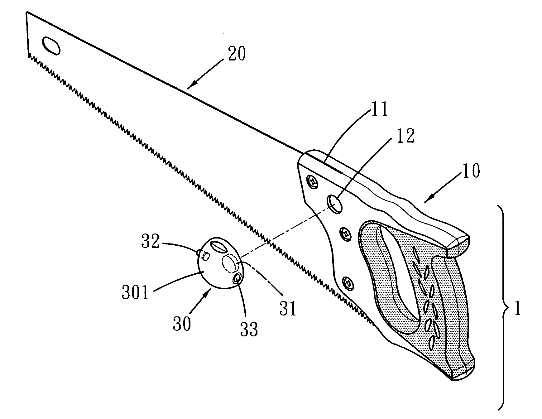
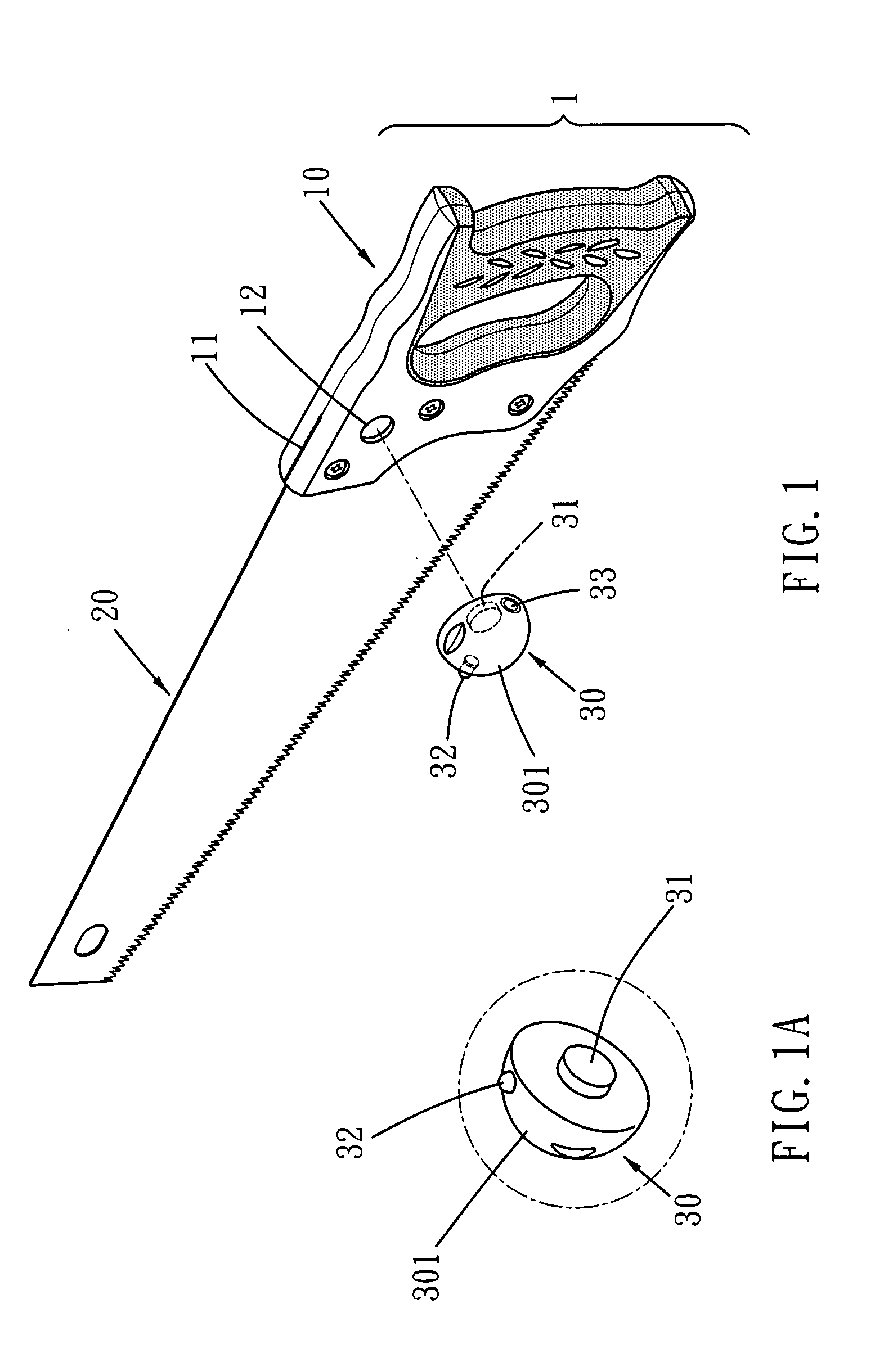
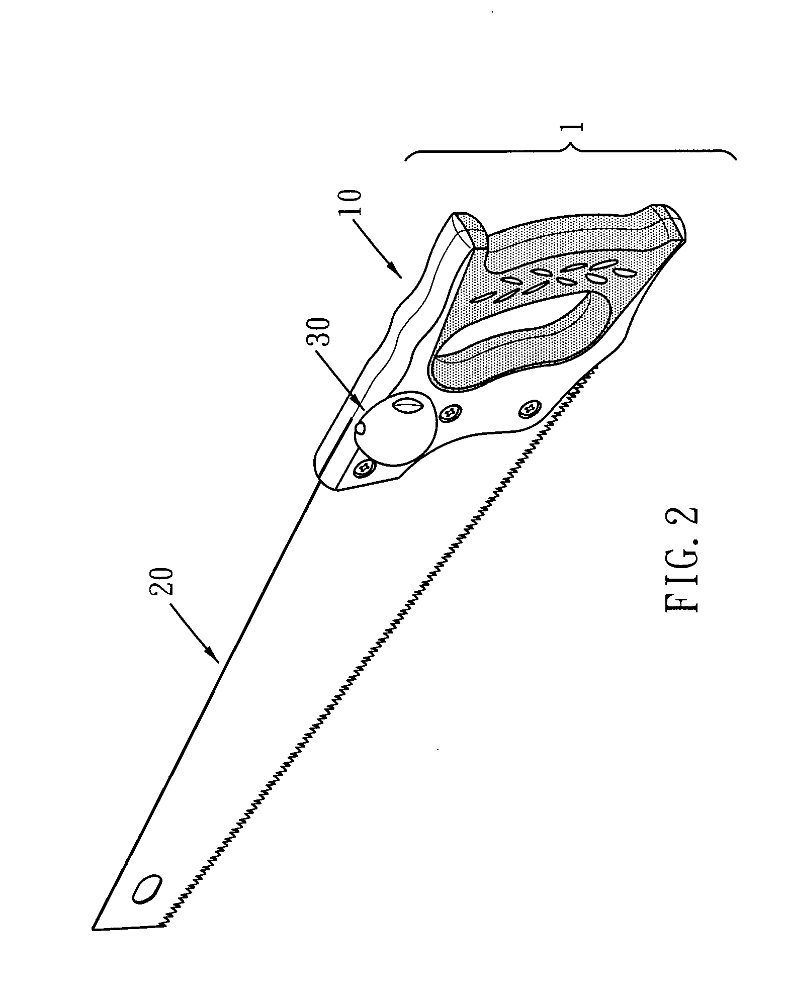
[0015]Referring to FIGS. 1, 1A and 2, the saw 1 includes a handle 10 which has a slit 11 defined in an end thereof and an end of a blade 20 is securely inserted into the slit 11. A recess 12 is defined in a side of the handle 10 and includes a magnetic inside. An illumination device 30 includes semi-spherical case 301 in which circuit board, wires and battery are received. A light emitting member 32 and a switch 33 are connected to an outer surface of the semi-spherical case 301. A protrusion 31 extends from an underside of the semi-spherical case 301 and is rotatably attracted to the magnetic inside of the recess 12. The light emitting member 32 can be a light emitting diode and the number of the light emitting member 32 can be multiple.

[0016]As shown in FIGS. 4 and 5, the light beam from the light emitting member 32 illuminates the object to be cut and the light emitting member 32 does not occupy too much space so that it does not affect the use of the saw 1.

[0017]As shown in FIGS...


PUM

PropertyMeasurementUnit
Magnetismaaaaaaaaaa

Abstract

A saw includes a handle and a blade which is fixed to the handle. The handle includes a recess defined in a side thereof and an illumination device is rotatably connected to the recess of the handle. The illumination device includes a light emitting member and a switch connected thereto. The user may rotate the illumination device to adjust the direction of the light beam from the light emitting member.

Description

BACKGROUND OF THE INVENTION[0001](1) Field of the Invention[0002]The present invention relates to a rotatable illumination device connected to a handle of a hand tool such as a saw so as to provide illumination feature.[0003](2) Description of the Prior Art[0004]A conventional illumination device generally is fixed to the handle of a hand tool and emits a light beam to form a guide line on the object to be cut. However, once the illumination device on a hand tool is damaged, the whole handle has to be replaced. Another illumination device for a saw 40 is shown in FIG. 6 and the saw 40 generally includes a blade 41 and a handle 42 which has a rail 421 extending from an underside thereof and an extension 50 has a groove 51 with which the rail 421 is engaged. A light unit 52 is connected to the extension 50 so as to emit a light beam to illuminate the object. However, the extension 50 increases the space required when operating the saw 40 so that the extension 50 may not be inserted in...

Claims


Application Information

Patent Timeline
IPC IPC(8): B25B23/18
CPCB23D59/00B27B21/04B23D59/002
Inventor HUANG, HUNG-HE
Owner HUANG HUNG HE
Learn More