Eureka AIR delivers breakthrough ideas for toughest innovation challenges, trusted by R&D personnel around the world.

Method of and system for planning a surgery

a surgery and surgery technology, applied in the field of surgery planning, can solve the problems of limited prosthesis size, limited prosthesis placement, and limited prosthesis placement,

Active Publication Date: 2009-02-12
STRYKER EURO OPERATIONS HLDG LLC
View PDF99 Cites 278 Cited by
  • Summary
  • Abstract
  • Description
  • Claims
  • Application Information

AI Technical Summary

Benefits of technology

[0013]In one embodiment of the invention, a system for assessing a fit of a femoral implant to a distal end of a femur in a selected orientation prior to resecting the femur includes means for obtaining pre-defined form factor information for plurality of femoral implants and means for obtaining surface shape information of the distal end of

Problems solved by technology

The method of visually choosing and adjusting the prosthesis can give rise to certain challenges.
One challenge—choosing the correct size of prosthesis—is limited by the ability of the surgeon to choose the correct size based solely on the map information of the bones.
Another challenge—positioning the prosthesis in the best arrangement with respect to the bone—is limited by both by the size of the prosthesis chosen by the surgeon and the ability of the surgeon to visualize the optimum positional arrangement.
A detriment to choosing a non-optimal position and / or size of the prosthesis may be the creation of a notch or an area where the edge of the prosthesis and the surface of the bone do not align well and require an undesirably large runout of the resected portion of the bone beyond an end of the prosthesis or a large overhang or gap between the end of the prosthesis and uncut portions of the bone.

Method used


Image

  • Method of and system for planning a surgery
  • Method of and system for planning a surgery
  • Method of and system for planning a surgery

Examples


Embodiment Construction

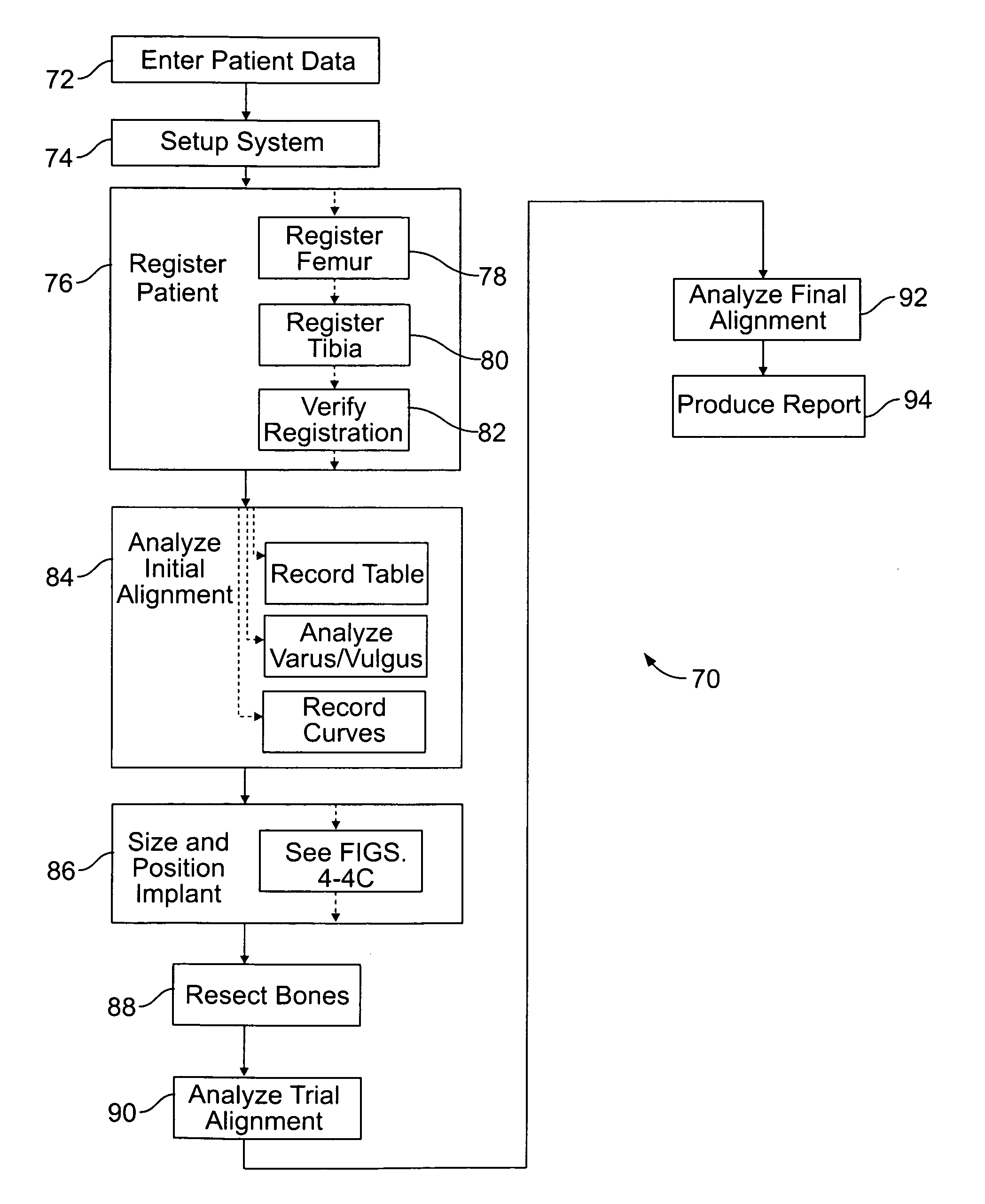
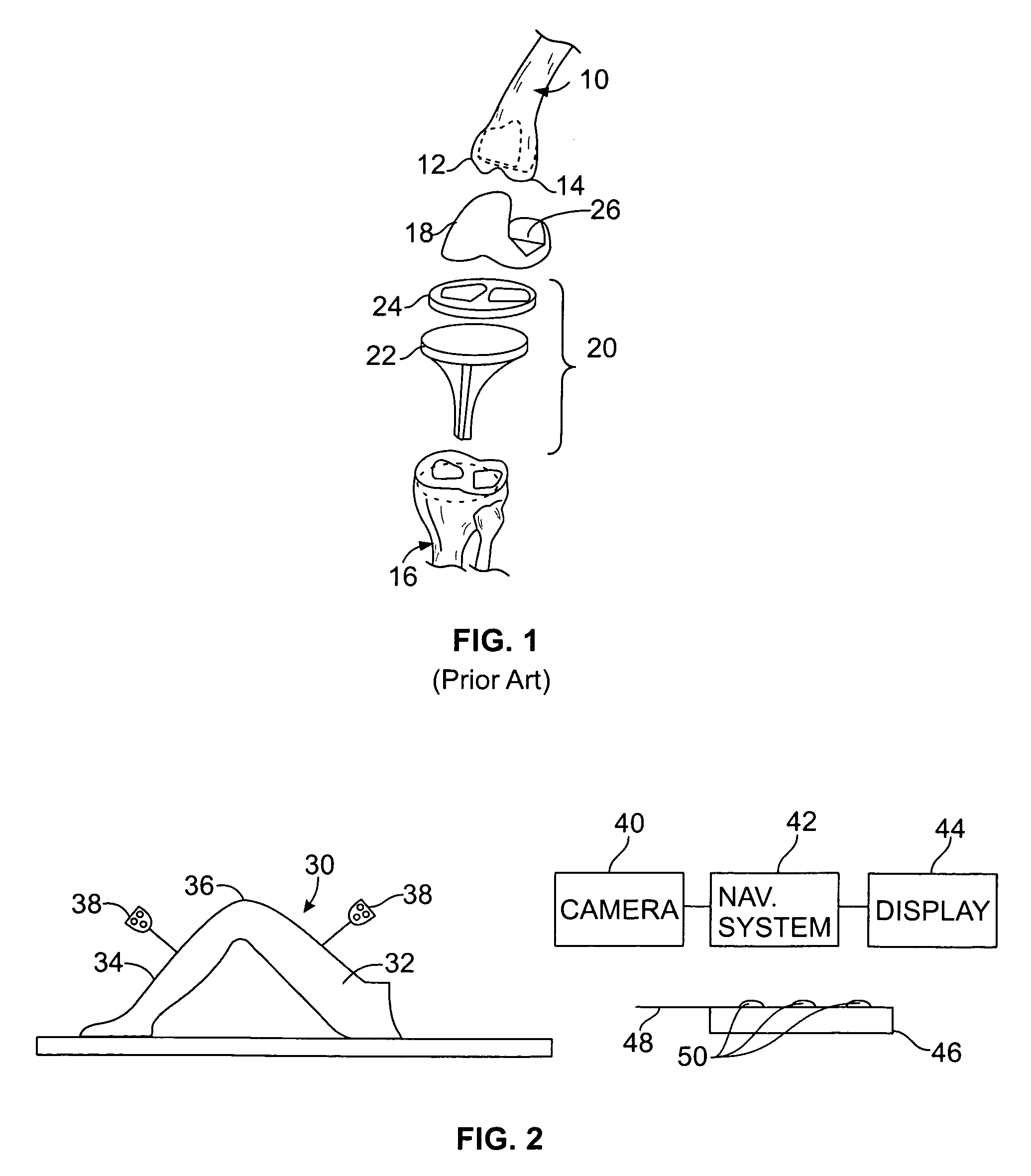
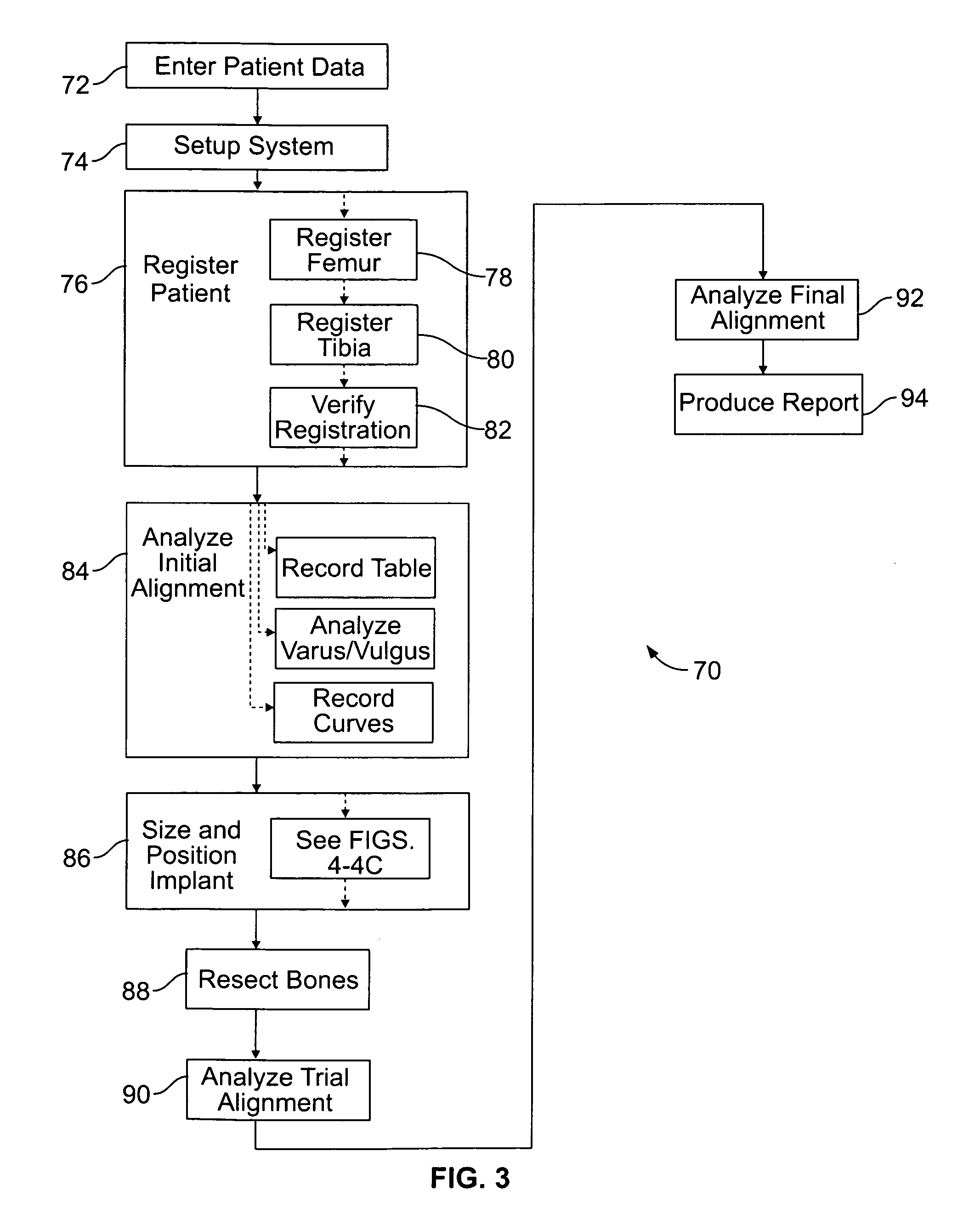
[0050]As diagrammatically shown in FIG. 2, a patient's leg 30 may be prepared for knee replacement surgery with the leg 30 bent so that the patient's upper leg or femur 32 is at an angle of approximately 90 degrees to the patent's lower leg or tibia 34. This positioning of the leg 30 places the patient's knee 36 in position for the procedure. Two tracking devices 38 that can communicate with a camera 40 associated with a computer assisted surgical navigation system 42 are associated with the femur 32 and the tibia 34 such that the tracking devices 38 move with the femur 32 and the tibia 34, respectively. The association can be by direct attachment to the respective bones or by other possible association methods. The computer assisted surgical navigation system 42 is, in one embodiment, one that is well known in the art and will not be further discussed here. Suitable surgical navigation systems 42 are described in U.S. Patent Publication No. 2001 / 0034530. A typical navigation system...


PUM


Abstract

A system for virtually planning a size and position of a prosthetic implant for a bone on a patient includes a database containing pre-defined form factor information for a plurality of different implants and a circuit for obtaining surface shape information of the bone. The system further includes a circuit for defining baseline location parameters for an implant location in relation to a virtual representation of the bone based on the surface shape information and a circuit for assessing a fit calculation of each implant in relation to the virtual representation of the bone based on the form factor in formation and a plurality of fit factors at each of a plurality of incremental positions in relation to the bone. Still further, the system includes a circuit for selecting a best fit implant size and position from all of the fit calculations.

Description

CROSS REFERENCE TO RELATED APPLICATIONS[0001]This application claims the benefit of U.S. Patent Application No. 60 / 963,738, filed Aug. 7, 2007, and claims benefit of U.S. Patent Application No. 60 / 963,916, filed Aug. 8, 2007, each of which is incorporated by reference herein in its entirety.REFERENCE REGARDING FEDERALLY SPONSORED RESEARCH OR DEVELOPMENT[0002]Not applicableSEQUENTIAL LISTING[0003]Not applicableBACKGROUND[0004]1. Field of the Disclosure[0005]The present disclosure relates generally to a method of and system for planning a surgery, such as selecting a size and position for an orthopedic prosthesis implant.[0006]2. Background[0007]Computer aided surgical systems for orthopedic and / or arthroplasty procedures are useful for both planning and executing various procedures. One known system and method is described in U.S. patent application Ser. No. 11 / 290,039, filed Nov. 30, 2005, which is incorporated by reference in its entirety herein. Another known system and method is ...

Claims


Application Information

Patent Timeline
IPC IPC(8): G06G7/60G06F9/455
CPCA61B17/1764A61B19/50A61B19/52A61B19/56A61B2017/0268G06F17/50A61B2019/507A61B2019/5268A61B2019/562A61B2019/564G06F19/3437A61B2019/501A61B2034/101A61B90/36A61B2034/2068A61B2034/254A61B34/25A61B34/10A61B2034/107A61B2034/252G16H50/50G06F30/00
Inventor AXELSON, STUART L.RUEBER, JENSMOCTEZUMA DE LA BARRERA, JOSE LUISZIMMERMAN, PETER
Owner STRYKER EURO OPERATIONS HLDG LLC
Why Eureka
Eureka Blog
Learn More