
Systems and Methods for Model-Based Sensor Fault Detection and Isolation

a sensor and model-based technology, applied in the direction of process and machine control, testing/monitoring control system, instruments, etc., can solve the problems of sensor failure, false fault detection, and control model failure to effectively operate the gas turbine engin

Inactive Publication Date: 2009-02-12
GENERAL ELECTRIC CO
View PDF14 Cites 25 Cited by
  • Summary
  • Abstract
  • Description
  • Claims
  • Application Information

AI Technical Summary

Benefits of technology

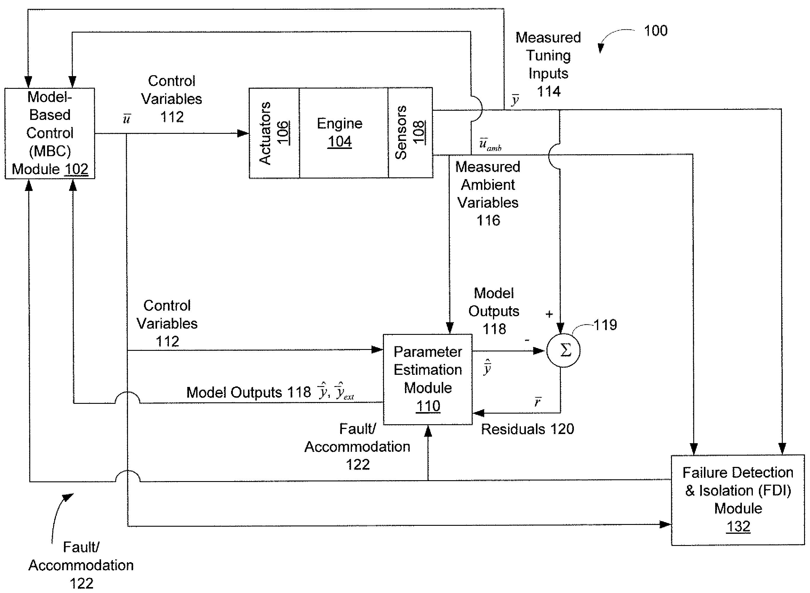
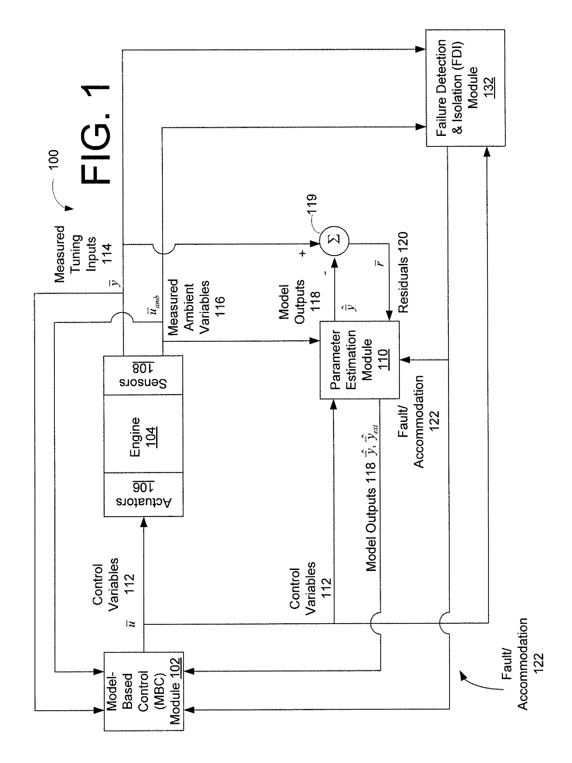
[0007]Embodiments of the invention may provide for model-based sensor fault detection and isolation (FDI) that improves control system reliability. With such a model-based FDI, a faulty sensor can be detected and isolated. The faulted sensor input may then be replaced with a model estimated value, and the system models can be adjusted online to be up-to-date with the real system operation.

Problems solved by technology

However, when one or more sensors fail or otherwise provide inaccurate data, the control models do not operate the gas turbine engines effectively.
Indeed, when the utilized model does not match with the real system operation, then sensor failure misses and false fault detections oftentimes occur.

Method used


Image

  • Systems and Methods for Model-Based Sensor Fault Detection and Isolation
  • Systems and Methods for Model-Based Sensor Fault Detection and Isolation
  • Systems and Methods for Model-Based Sensor Fault Detection and Isolation

Examples


Embodiment Construction

[0021]The present invention now will be described more fully hereinafter with reference to the accompanying drawings, in which embodiments of the invention are shown. This invention may, however, be embodied in many different forms and should not be construed as limited to the embodiments set forth herein; rather, these embodiments are provided so that this disclosure will be thorough and complete, and will fully convey the scope of the invention to those skilled in the art. Like numbers refer to like elements throughout.

[0022]Embodiments of the invention are described below with reference to block diagrams and flowchart illustrations of systems, methods, apparatuses and computer program products. It will be understood that each block of the block diagrams and flowchart illustrations, and combinations of blocks in the block diagrams and flowchart illustrations, respectively, can be implemented by computer program instructions. These computer program instructions may be loaded onto a...


PUM


Abstract

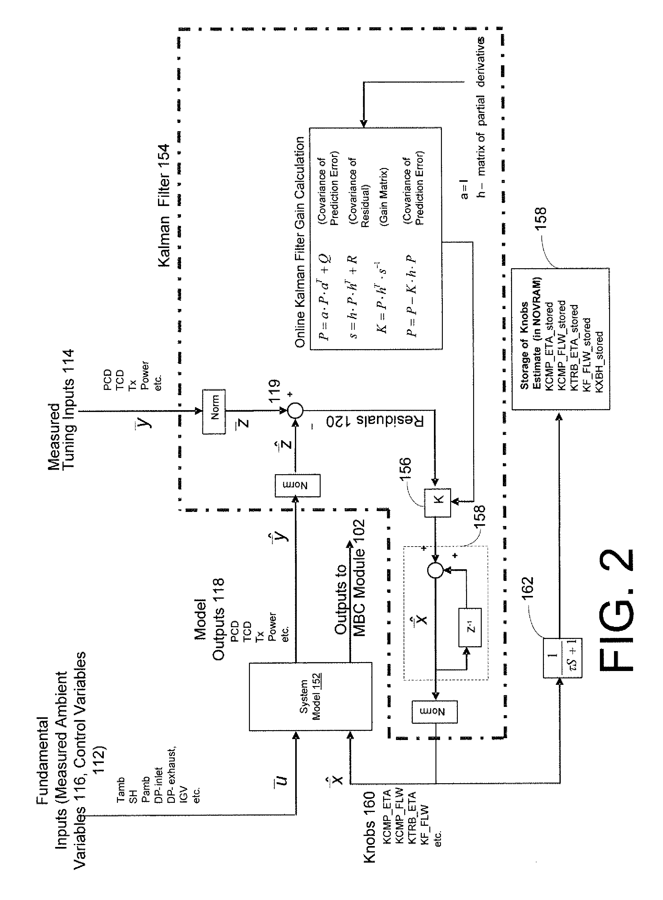
The systems and method may include receiving a plurality of measured tuning inputs associated with an operating parameter of an engine, providing a plurality of parameter estimation modules that utilize one or more component performance maps having adjustable knobs to generate model outputs, where each parameter estimation module is configured independently of a respective one of the operating parameters of the engine, and where each parameter estimation module generates the model outputs based upon fundamental inputs associated with the engine. The systems and methods may further include calculating residual values for each parameter estimation module, adjusting knobs of each parameter estimation module, and determining that a sensor associated with a measured tuning input or a fundamental input is faulty based at least in part upon values of the knobs and residual values.

Description

BACKGROUND OF THE INVENTION[0001]1. Field of the Invention[0002]Aspects of the present invention relate generally to sensor fault detection and isolation and more particularly, to model-based sensor failure detection and isolation for engines such as gas turbine engines.[0003]2. Description of Related Art[0004]The control and operation of current gas turbine engines depends heavily on information received from sensors. In particular, the data received from the sensors is used by control models to determine whether any control adjustments are to be made. However, when one or more sensors fail or otherwise provide inaccurate data, the control models do not operate the gas turbine engines effectively.[0005]Current fault detection and isolation methods are effective only when the utilized system model matches the real system operation. Indeed, when the utilized model does not match with the real system operation, then sensor failure misses and false fault detections oftentimes occur. Th...

Claims


Application Information

Patent Timeline
IPC IPC(8): G01M15/00
CPCG05B23/0254G05B9/02
Inventor VERSHININ, MIKHAILHEALY, TIMOTHY ANDREWFREDERICK, GARTH CURTIS
Owner GENERAL ELECTRIC CO
Learn More