
Method and apparatus for processing signals of photo-detector in visible light communication system

a technology of visible light communication system and signal processing method, which is applied in the direction of electrical apparatus, electromagnetic transmission, close-range type systems, etc., can solve the problems of reducing the operation speed of the photodiode, increasing the strength of output electrical signals, and reducing the reaction speed of the detector, so as to restore the reliability of the incoming signal

Active Publication Date: 2009-02-12
SAMSUNG ELECTRONICS CO LTD
View PDF3 Cites 25 Cited by
  • Summary
  • Abstract
  • Description
  • Claims
  • Application Information

AI Technical Summary

Benefits of technology

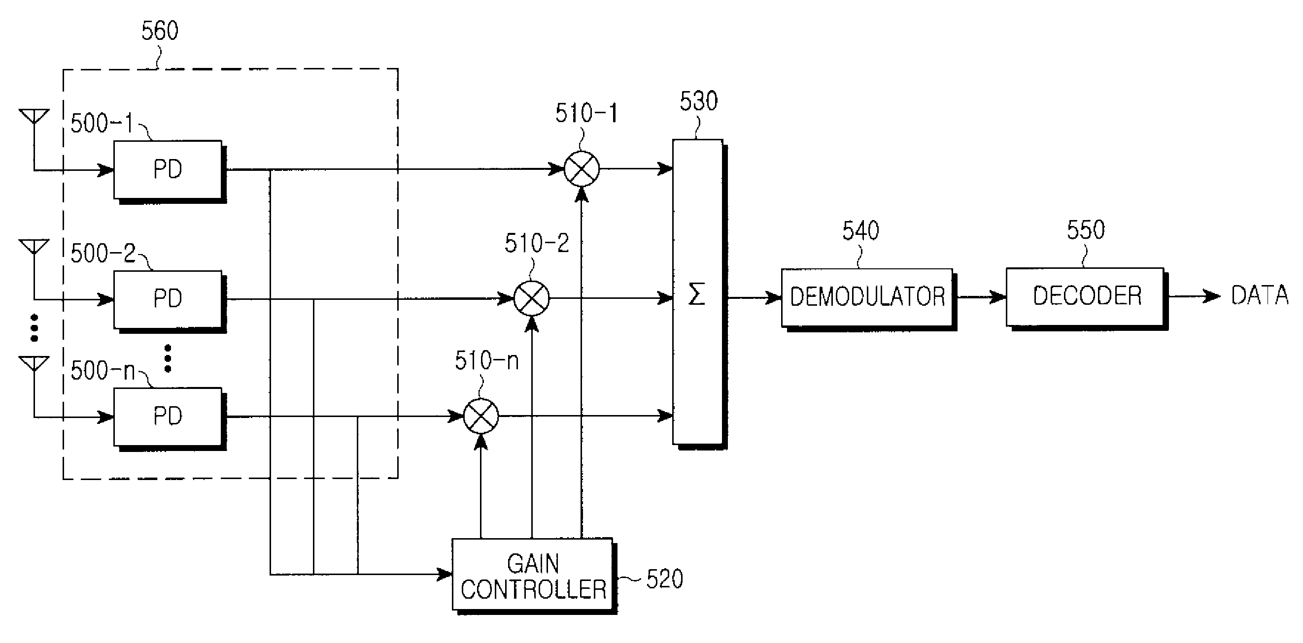
[0018]Accordingly, the present invention provides a method and an apparatus for processing signals in a visible light communication system, which can restore incoming signals with reliability by combining output signals of a plurality of photodiodes having different areas from one another.

Problems solved by technology

In general, an increase in the photodiode area increases a corresponding light-receiving amount, but reduces the operation speed of the photodiode.
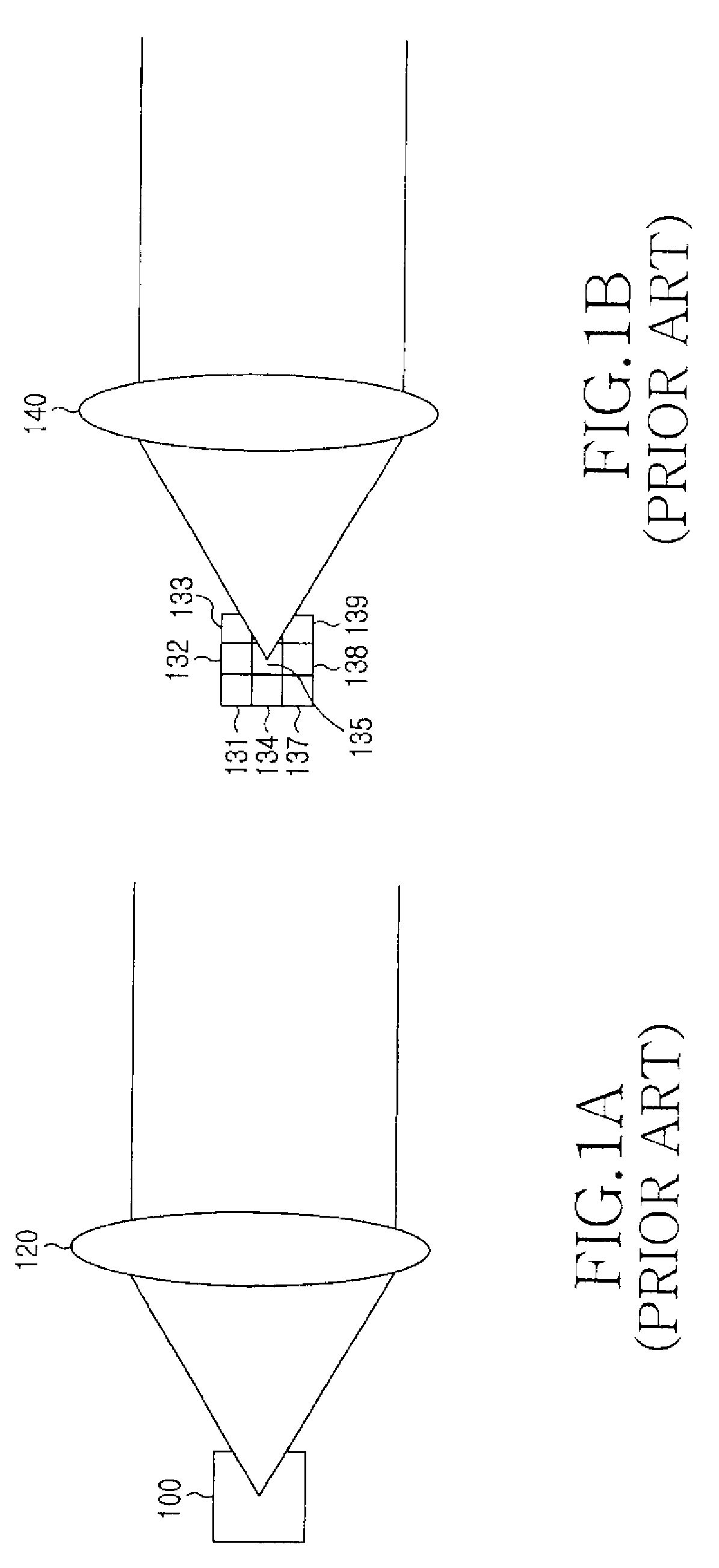
However, in the visible light communication using a free space propagation scheme, visible light signals with information illuminates wide free space during transmission, so that the visible light communication receiver receives only a part of signals transmitted from the visible light communication transmitter.
Therefore, as the area of the photo-detector gets larger, the amount of receivable light increases, which increases strengths of output electrical signals while decreasing the reaction speed of the detector.
In other words, when the speed of change of the transmitted light by increase of the transmission speed is beyond the operation limit of the photo-detectors, the normal reception operation may not be performed.
However, in this case, an increase in complexity relatively increases cost.

Method used


Image

  • Method and apparatus for processing signals of photo-detector in visible light communication system
  • Method and apparatus for processing signals of photo-detector in visible light communication system
  • Method and apparatus for processing signals of photo-detector in visible light communication system

Examples


Embodiment Construction

[0035]Hereinafter, an apparatus and an operation method for exemplary embodiments of the present invention will be described with reference to the accompanying drawings.

[0036]The present invention provides a method for applying a suitable gain value to a photodiode array including a plurality of photodiodes, so as to restore necessary visible light signals during reception of visible light signals.

[0037]Hereinafter, a method and an apparatus for processing signals of photo-detectors in a visible light communication system according to one embodiment of the present invention will be described in more detail with reference to the following drawings.

[0038]FIGS. 4A and 4B are views schematically illustrating a visible light receiving unit of the visible light communication receiver according to an exemplary embodiment of the present invention.

[0039]FIG. 4A shows a photodiode array 410 (hereinafter, referred to as “PD array”) including a plurality of photodiodes having a plurality of dif...


PUM


Abstract

Disclosed is a method for processing incoming signals of photo-detectors in a visible light communication system. The method includes: dividing symbol duration into divided durations according to an equal time interval to set the divided durations to a plurality of time slots, the symbol duration being a time required to transmit one of a symbol and a bit; receiving visible light signals through a photodiode array in a receiver; determining a gain value of each of the photodiodes during a time slot, in consideration of each photodiode area on the photodiode array during the time slot and the time slot position within the symbol duration; multiplying a gain value of each of the photodiodes by an output value of a corresponding photodiode; and summing up output values of each of the photodiodes by which the gain value has been multiplied and calculating a total of output values of the time slot.

Description

CLAIM OF PRIORITY[0001]This application claims the benefit under 35 U.S.C. §119(a) of an application entitled “Method and Apparatus For Processing Signals Of Photo-Detector In Visible Light Communication System” filed in the Korean Intellectual Property Office on Aug. 10, 2007 and assigned Serial No. 2007-80638, the entire contents of which are hereby incorporated by reference.BACKGROUND OF THE INVENTION[0002]1. Field of the Invention[0003]The present invention relates to a visible light communication system, and more particularly, to a method and an apparatus for processing incoming signals in a visible light communication receiver using a plurality of photo-detectors.[0004]2. Description of the Related Art[0005]Recently, with improvement in the luminance efficiency of Light Emitting Diodes (LEDs) and a price drop of the LEDs, the use of LEDs has widely spread in general lighting markets, including the markets of fluorescent lamps and incandescent lamps, as well as specific lightin...

Claims


Application Information

Patent Timeline
IPC IPC(8): H04B10/06
CPCH04B10/1121H04B10/116H04B10/60
Inventor ANN, JONG-HOONSON, JAE-SEUNGWON, EUN-TAE
Owner SAMSUNG ELECTRONICS CO LTD
Learn More