Variable compression ratio device for internal combustion engine
a compression ratio and internal combustion engine technology, applied in the direction of engine controllers, machines/engines, mechanical devices, etc., can solve the problems of reducing reduce the bending stress reduce the rigidity of the actuator rod, and increase the bending stress in the interior of the actuator rod
- Summary
- Abstract
- Description
- Claims
- Application Information
AI Technical Summary
Benefits of technology
Problems solved by technology
Method used
Image
Examples
first embodiment
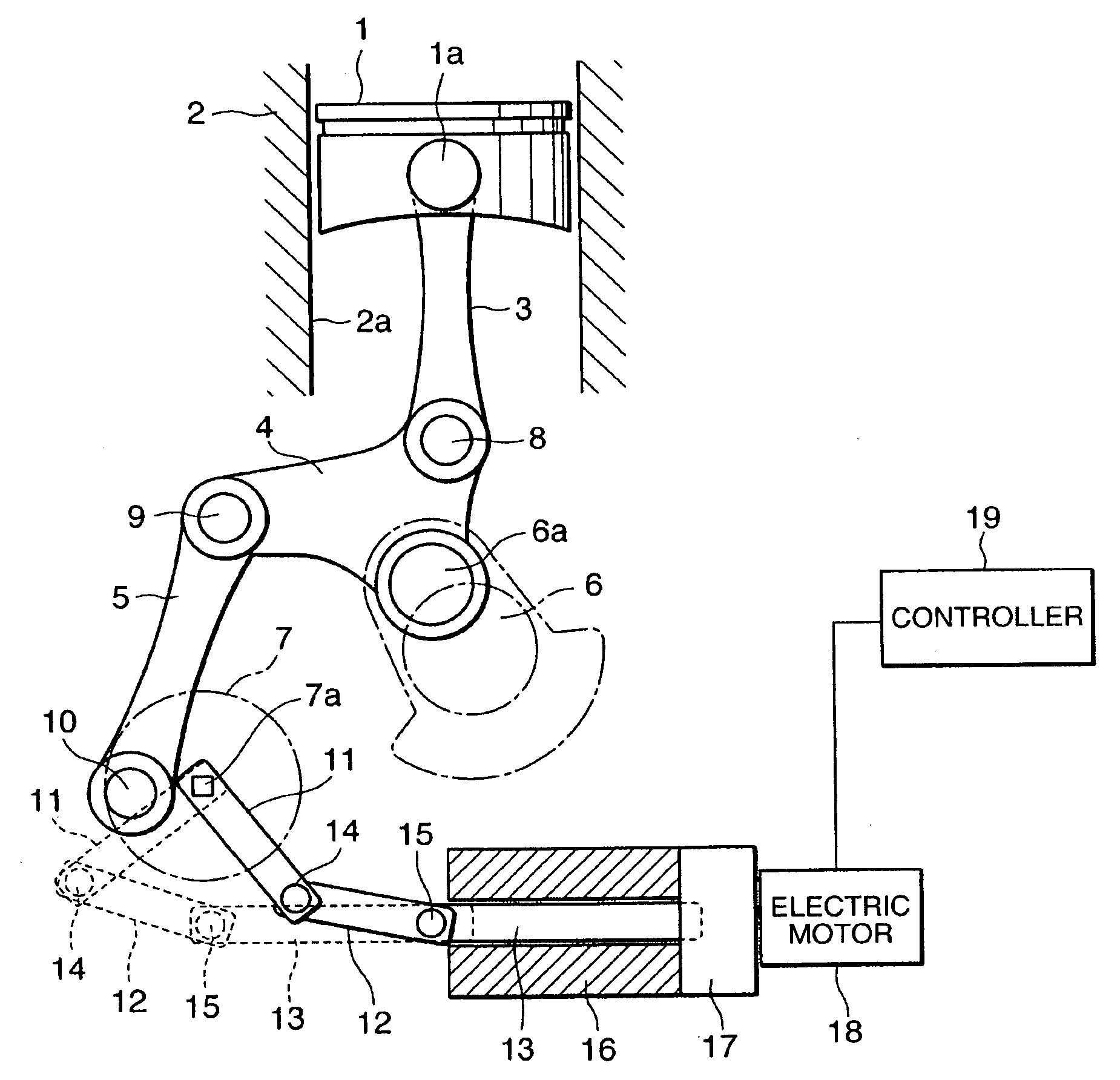
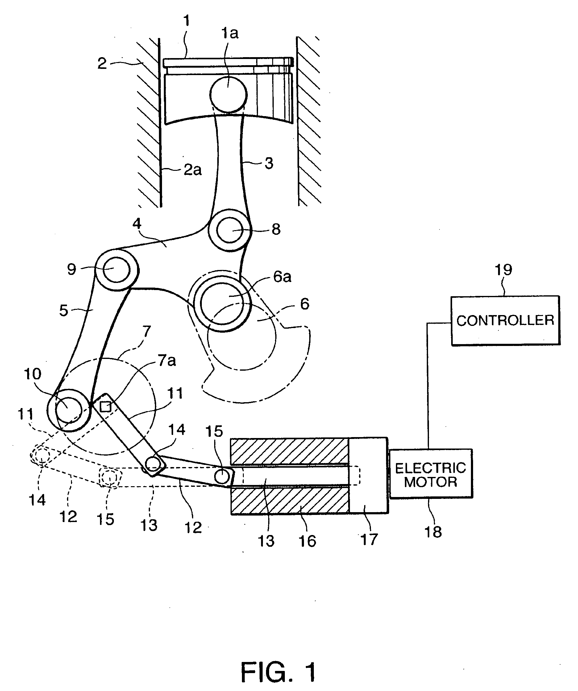
[0083]Similarly to the first embodiment, a variable compression ratio device according to this embodiment is constituted such that the movement amount of the actuator rod 13 per rotation angle of the control shaft 7 is larger at a high compression ratio than a low compression ratio.
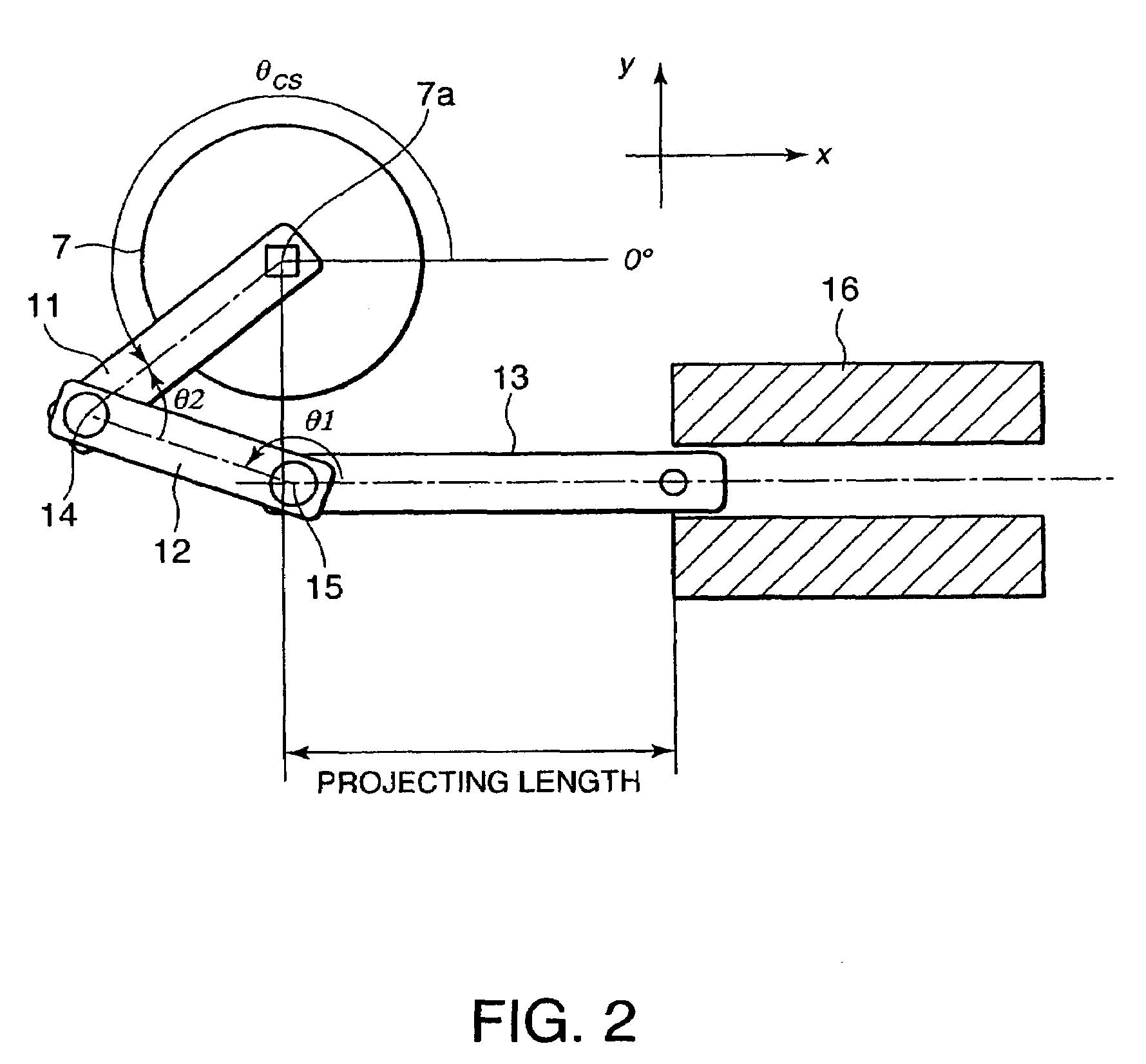
[0084]As shown in FIG. 12, the rotation angle θcs of the control shaft 7 is set to be close to 180 degrees at the minimum compression ratio and to be close to 270 degrees at the maximum compression ratio.
[0085]By means of this setting, the compression ratio increases as the rotation angle θcs of the control shaft 7 increases. However, in contrast to the first embodiment, the increase rate of the compression ratio per unit rotation angle decreases as the rotation angle θcs of the control shaft 7 increases as shown in FIG. 13. In other words, variation in the compression ratio relative to variation in the rotation angle θcs of the control shaft 7 decreases as the compression ratio approaches the maximum com...
third embodiment
[0086]Referring to FIGS. 14A and 14B, FIGS. 15-17, FIGS. 22A and 22B, FIGS. 23A-23G, and FIGS. 24A-24G, this invention will be described.
[0087]FIG. 14A shows the state of the variable compression ratio device in the vicinity of the minimum compression ratio. FIG. 14B shows the state of the variable compression ratio device in the vicinity of the maximum compression ratio.
[0088]In this embodiment, similarly to the first embodiment, the rotation angle θcs of the control shaft 7 at the minimum compression ratio is close to 90 degrees, and the rotation angle θcs of the control shaft 7 at the maximum compression ratio is close to 180 degrees. Accordingly, the effective arm length by which a load F3 acting on the control shaft 7 is converted into the control shaft torque Tcs reaches a maximum at the maximum compression ratio.
[0089]Further, the fixing lever 11, connecting link 12, and actuator rod 13 are disposed such that the angle θ2 formed by the connecting link 12 and the actuator rod ...
fourth embodiment
[0118]Referring to FIGS. 18-21, this invention will be described.
[0119]A variable compression ratio device according to this embodiment differs from the first embodiment in the displacement region of the offset pin 10, the connecting pin 14, and the connecting pin 15.
[0120]Referring to FIG. 18, in the variable compression ratio device according to this embodiment, the offset pin 10 displaces over the second quadrant and third quadrant so as to be positioned in the second quadrant at the minimum compression ratio and in the third quadrant at the maximum compression ratio.
[0121]The connecting pin 14 displaces over the third quadrant and fourth quadrant so as to be positioned in the third quadrant at the minimum compression ratio and in the fourth quadrant at the maximum compression ratio. Furthermore, the connecting pin 14 is positioned above the axis of the actuator rod 13 throughout the entire displacement region, and comes closest to the axis of the actuator rod 13 at the intermedi...
PUM
 Abstract
Description
Claims
Application Information
 - R&D
- Intellectual Property
- Life Sciences
- Materials
- Tech Scout
- Unparalleled Data Quality
- Higher Quality Content
- 60% Fewer Hallucinations
Browse by: Latest US Patents, China's latest patents, Technical Efficacy Thesaurus, Application Domain, Technology Topic, Popular Technical Reports.
© 2025 PatSnap. All rights reserved.Legal|Privacy policy|Modern Slavery Act Transparency Statement|Sitemap|About US| Contact US: help@patsnap.com


