
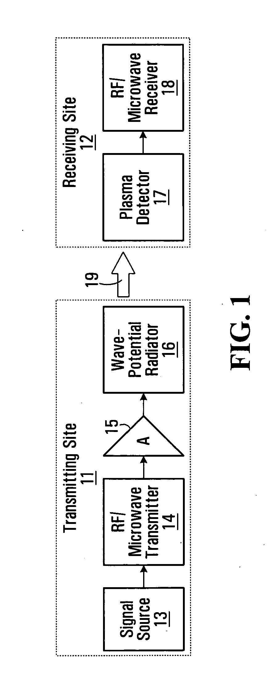
Electromagnetic wave-potential communication system

a communication system and electromagnetic wave technology, applied in the field of electromagnetic communication systems, can solve the problems of no published data on the realization of optical experiments, no successful a-detection experiments in the classical macroscopic sense involving time-varying signals, and need a cryogenic environment to achieve the effect of improving matching

Inactive Publication Date: 2009-02-05
MCMASTER UNIV
View PDF10 Cites 7 Cited by
  • Summary
  • Abstract
  • Description
  • Claims
  • Application Information

AI Technical Summary

Benefits of technology

[0017]In some embodiments, the wave-potential receiver further comprises a balun to improve matching between the at least one biased plasma device and the radio receiver circuitry.
[0018]In some embodiments, the radio receiver circuitry switches the polarity of the current to the wave-potential detector between a first polarity and a second polarity and takes the difference between a received signal received during the first polarity from a received signal received during the second polarity to suppress real-power (E,B) signal interference.

Problems solved by technology

To date, there are no successful A-detection experiments in the classical macroscopic sense involving time-varying signals, e.g., radio-frequency or microwave signals.
However, there is no published data on the realization of this optical experiment.
Their major drawback is that they require a cryogenic environment in order to achieve the superconducting state.
In U.S. Pat. No. 4,432,098, transfer of information utilizing such signals is also proposed, but no practical communication system for implementing such a transfer is disclosed.
The proposed system uses a transmission device, which is quasi-static in nature, and whose signals are to be detected in the device's near zone, which severely limits the distance over which the signals can be detected.
Such a design principle leads to a substantial conventional (E,B) signal in the far zone compared to the pure-potential signal, thereby inevitably leading to substantial power consumption and, possibly, interference.

Method used


Image

  • Electromagnetic wave-potential communication system
  • Electromagnetic wave-potential communication system
  • Electromagnetic wave-potential communication system

Examples


Embodiment Construction

[0058]In the following detailed description of sample embodiments of the invention, reference is made to the accompanying drawings which form a part hereof, and in which is shown by way of illustration specific sample embodiments in which aspects of the invention may be practiced. These embodiments are described in sufficient detail to enable those skilled in the art to practice the invention, and it is to be understood that other embodiments may be utilized and that logical, mechanical, electrical, and other changes may be made without departing from the scope of the invention. The following detailed description is, therefore, not to be taken in a limiting sense, and the scope is defined by the appended claims.

[0059]As noted above, there are cases, where, for a particular antenna or another type of electromagnetic source, the field force vectors can be reduced to zero or near-zero in parts or sectors of space (or even all space) while the components of the 4-vector potential are si...


PUM


Abstract

A wave-potential detector and a wave-potential radiator are provided that detect and radiate wave-potential signals having longitudinally polarized A vectors, respectively. Wave-potential receivers and transmitters incorporating the wave-potential detector and wave-potential radiator, respectively, are also provided. The wave-potential detector includes a biased plasma device, having at least a portion of its bias current that is parallel to the direction of propagation of a wave-potential signal having a longitudinally polarized A vector. Both omnidirectional and directive wave-potential radiators are provided.

Description

RELATED APPLICATIONS[0001]This application claims the benefit of prior U.S. provisional application No. 60 / 953,773 filed Aug. 3, 2007 and prior U.S. provisional application No. 60 / 957,192 filed Aug. 22, 2007, which are hereby incorporated by reference in their entireties.FIELD OF THE INVENTION[0002]The present invention pertains to electromagnetic communication systems.BACKGROUND OF THE INVENTION[0003]Conventional RF and microwave long-distance communication systems are capable of receiving only signals whose field vectors E and B are nonzero, i.e., signals which carry real electromagnetic power as described by the Poynting vector. There are cases, however, where, for a particular antenna or another type of electromagnetic source, the field force vectors can be reduced to zero in parts or sectors of space (or even all space) while the components of the 4-vector potential (the magnetic vector potential A and the electric scalar potential Φ) are significantly different from zero.[0004...

Claims


Application Information

Patent Timeline
Patent Type & Authority Applications(United States)
IPC IPC(8): H03K9/00
CPCH01Q1/26H01Q21/24H01Q19/13
Inventor NIKOLOVA, NATALIA K.ZIMMERMAN, JR., ROBERT K.
Owner MCMASTER UNIV
Learn More