
Monitoring system and temperature controller

Inactive Publication Date: 2009-01-29
YAMATAKE HONEYWELL CO LTD
View PDF1 Cites 3 Cited by
  • Summary
  • Abstract
  • Description
  • Claims
  • Application Information

AI Technical Summary

Benefits of technology

[0008]The present invention has been made to solve the problems as mentioned above. The primary object thereof is to provide a monitoring system simple in structure and allowing, for example, a failure of the body or a temperature sensor of a temperature controller, an abnormal state of a temperature-controlled object, etc. to be visually recognized (grasped) easily on a display device incorporated therein, and a temperature controller incorporating such monitoring system.
[0010]In this monitoring system, the display device presents an abnormality display in the manner that varies depending on whether an abnormality signal and a latch signal are each transmitted or not, thereby notifying occurrence of an abnormality, precisely, simply and effectively.
[0012]In this aspect, the varying manner of the display device's presenting an abnormality display allows precise recognition of whether an abnormality previously detected still continues or an abnormality has just occurred or an abnormality previously detected is gone.
[0020]This temperature controller likewise allows precise recognition of whether an transmission-line failure in the temperature sensor previously detected still continues or a transmission-line failure has just occurred or a transmission-line failure previously detected is gone, thereby providing an effective assistance in dealing with transmission-line failures in the temperature controller.

Problems solved by technology

As an example, that a failure of the temperature sensor to be detected can be a conductor breakage in a sheathed thermocouple.
In such cases, since the conventional temperature controller is configured to present a warning display only when a conductor breakage is detected, there is a risk that the warning display is overlooked so that the conductor breakage in the sheathed thermocouple fails to be recognized, unless the display device is always monitored.
In such temperature controllers, however, the failure cannot be recognized unless event information supplied from the temperature controller to the outside is monitored by means of an external device such as a main control device.
Further, even when the failure of the body of the temperature controller is gone so that outputting of an abnormality detection signal stops, transmission of event information continues unless the latch circuit retaining the output state resulting from the receipt of an abnormality detection signal is reset.
This prevents an accurate grasp of the present situation.

Method used


Image

  • Monitoring system and temperature controller
  • Monitoring system and temperature controller
  • Monitoring system and temperature controller

Examples


Embodiment Construction

[0029]Referring to the drawings attached, as an embodiment of the present invention, a temperature controller incorporating a monitoring system according to the present invention will be described.

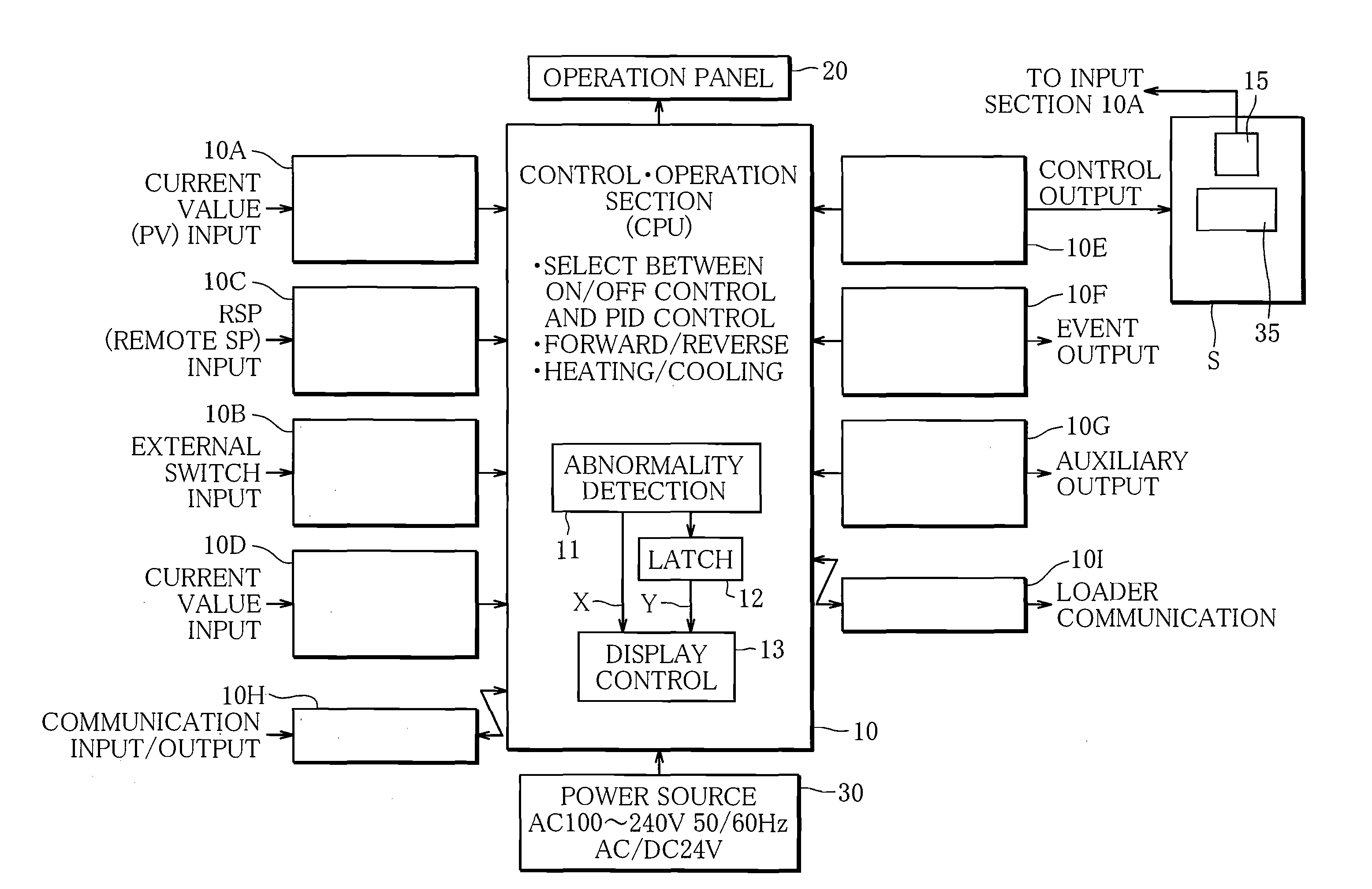
[0030]FIG. 1 is a functional block diagram schematically showing the structure of a temperature controller according to the present invention. The temperature controller includes a body, whose main component is a control-operation section 10 which is a CPU, an operation panel 20 constituting a man-machine interface for the control-operation section 10, and a power source section 30. A temperature sensor 15 is connected to an input section of the control-operation section 10, and a heating-cooling device 35 is connected to an output section thereof. Thus, the temperature controller controls the temperature of an object S by controlling the operation of the heating-cooling device 35 on the basis of a temperature of the object S detected by the temperature sensor.

[0031]Basically, the control-...


PUM


Abstract

The present invention provides A monitoring system comprising a display device, an abnormality detection means for monitoring an object and when detecting an abnormality of the monitored object, outputting an abnormality signal, and a display control means for causing the display device to present an abnormality display, further comprising a latch means for retaining the output state resulting from receipt of an abnormality signal, thereby continuing to output a latch signal until reset, and a reset device for resetting the latch device, wherein the display control device determines in what manner the display device presents an abnormality display, depending on whether an abnormality signal and a latch signal are each transmitted or not.

Description

CROSS-REFERENCE TO RELATED APPLICATION[0001]The present application claims priority under 35 U.S.C. §119 to Japanese Patent Application No. 2007-195958 filed on Jul. 27, 2007. The content of both applications are incorporated herein by reference in their entirety.BACKGROUND OF THE INVENTION[0002]1. Field of the Invention[0003]This invention relates to a monitoring system incorporated in a temperature controller or the like to monitor an object and present information about the state of the monitored object on a display device incorporated therein.[0004]2. Description of the Related Art[0005]Japanese Patent Application KOKAI Publication 2004-126732 (referred to as Patent Document 1) discloses a temperature controller for controlling temperature of a variety of temperature environments, etc. The temperature controller disclosed has a function of controlling the temperature of an object by obtaining a control output (MV value) to be supplied to a heating-cooling device on the basis of ...

Claims


Application Information

Patent Timeline
IPC IPC(8): G08B23/00
CPCG05B23/027Y10S345/904G05D23/2202G05B23/0272G05D23/1902G05D23/22G05D23/02
Inventor HIRAYAMA, HIROFUMI
Owner YAMATAKE HONEYWELL CO LTD
Learn More