
Automotive Door Handle Device

a technology for door handles and automotives, which is applied in the direction of doors, wing knobs, lock applications, etc., can solve the problem that the stopper member b>102/b> may not function normally, and achieve the effect of being movable more easily

Inactive Publication Date: 2009-01-29
ALPHA
View PDF10 Cites 18 Cited by
  • Summary
  • Abstract
  • Description
  • Claims
  • Application Information

AI Technical Summary

Benefits of technology

[0006]Incidentally, as a condition where the stopper member 102 surely carries out a function of the stopper, it is listed that, when the impact acceleration A is inputted to the door body, the stopper member 102 should reach the interfering position earlier than the engagement portion 101a of the handle 101. This condition is easily achievable by setting the stopper member 102 so as to be movable more easily than the handle 101 when the impact acceleration is inputted to the door body.
[0008]In this connection, it is an object of the present invention to provide an automotive door handle device in which the stopper member can surely inhibit the handle from moving in the opening position direction at the time of the side collision and so on.
[0016]In accordance with this configuration, a configuration of the movement resisting portion is simple.

Problems solved by technology

However, in the above-described conventional example, contrivance for allowing the stopper member 102 to stay in the interference enabled section for a long time is not made at all, and there is an apprehension that the stopper member 102 may not function normally.

Method used


Image

  • Automotive Door Handle Device
  • Automotive Door Handle Device
  • Automotive Door Handle Device

Examples


first embodiment

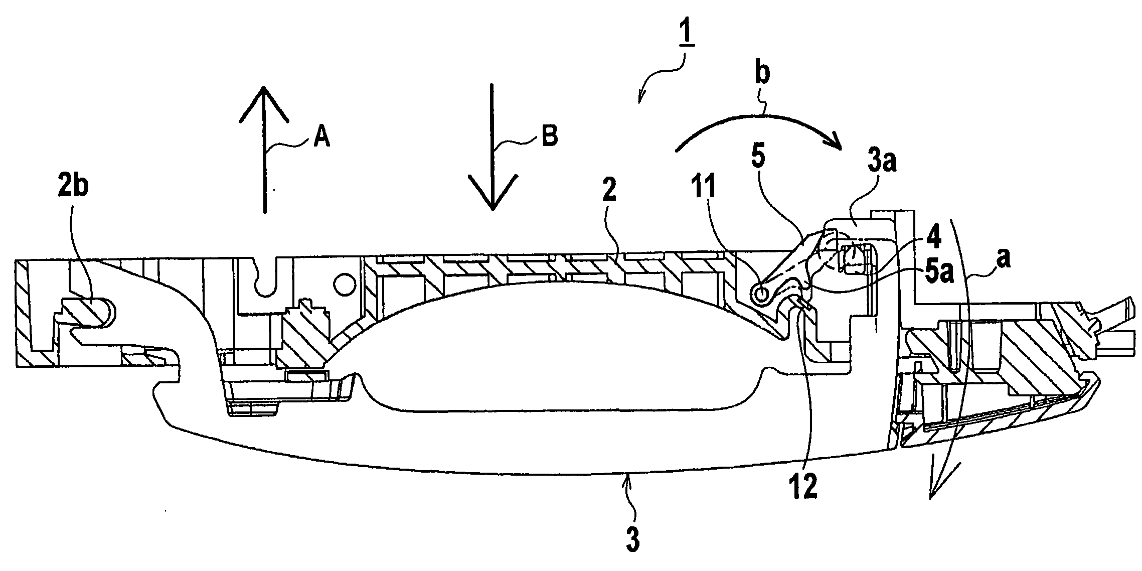
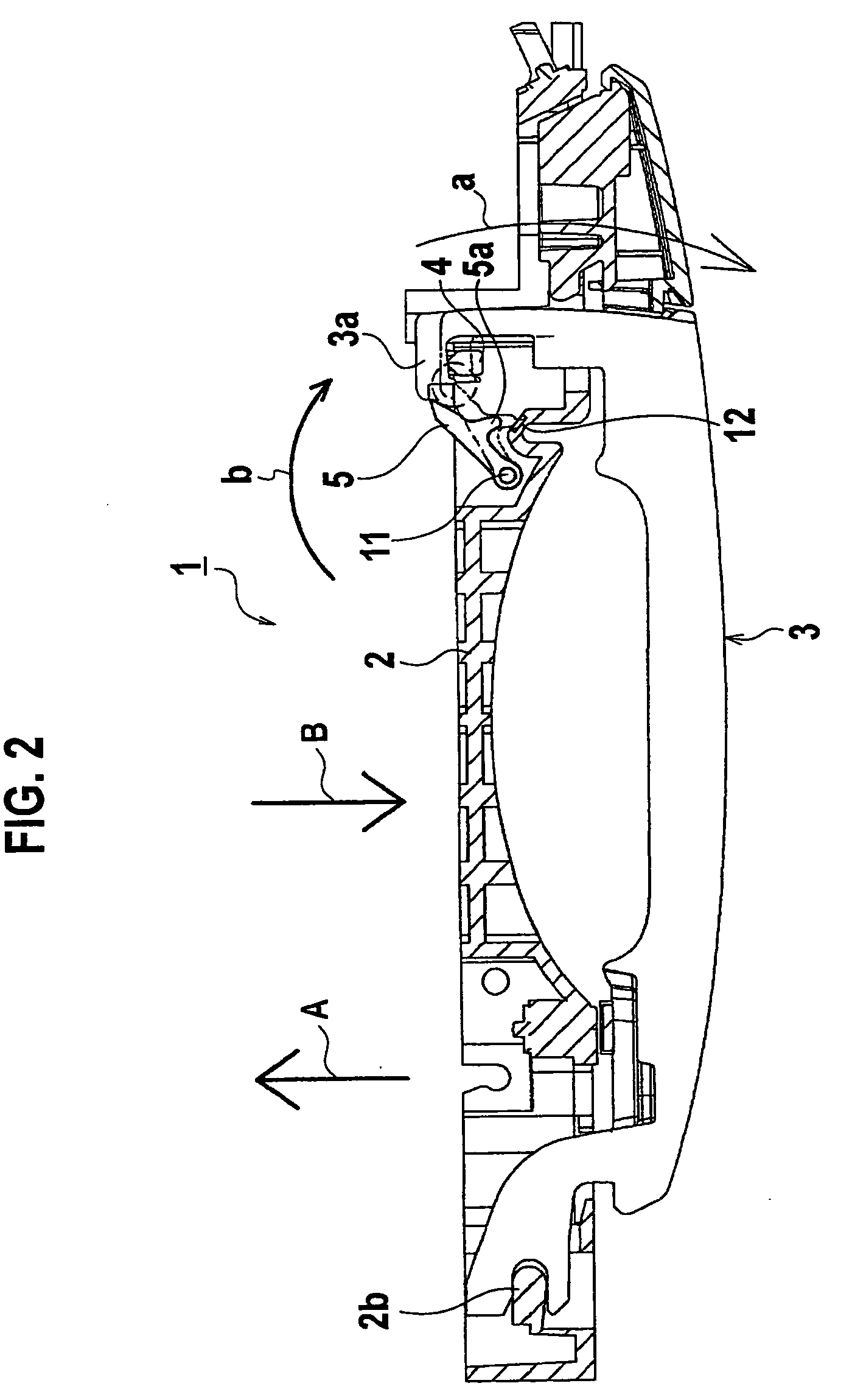
[0031]In FIG. 2 to FIG. 4, an automotive door handle device 1 includes: a bracket 2 as a door body side member fixed to a door body (not shown); a grip-type handle 3 provided on a support portion 2b of the bracket 2 so as to be freely rotatable; a lever 4 rotationally shifted from a waiting position to a lock releasing position in synchronization with a rotation operation of the handle 3; a door locking mechanism (not shown) coupled to the lever 4 while interposing a wire (not shown) therebetween; a stopper member 5 provided on the bracket 2 so as to be freely rotatable; and a spring 6 (shown in FIG. 3) as urging means for urging the stopper member 5 to a waiting position side. Note that, in FIG. 3, reference symbol A denotes a direction of an acceleration on a collision side, and reference symbol B denotes a direction of an acceleration on a non-collision side.

[0032]A most part of the handle 3 is exposed to an outside of a door panel (not shown), and the handle 3 is rotationally op...

second embodiment

[0039]FIG. 5 is a main portion cross-sectional view of peripheries of a stopper member and a handle according to a second embodiment of the present invention.

[0040]As shown in FIG. 5, stopper holding means of this second embodiment is composed of shock absorption members 12 and 13 provided on thrusting surfaces of both of the other-side rotation regulating portion 2a of the bracket 2 and the stopper-side rotation regulating portion 5a of the stopper member 5.

[0041]Other configurations are similar to those of the above-described first embodiment, and accordingly, a duplicate description will be omitted. Note that, in FIG. 5, the same reference numerals are assigned to the same constituent spots as those in the configuration of the above-described first embodiment, and clarification of the constituent spots concerned is achieved.

[0042]Also in this second embodiment, the bound speed of the stopper member 5 becomes slow, and accordingly, the door can be surely prevented from opening by ...

third embodiment

[0044]FIG. 6 and FIGS. 7(a) and 7(b) show a third embodiment of the present invention: FIG. 6 is a main portion cross-sectional view of peripheries of a stopper member and a handle; FIG. 7(a) is a plan view of a state where the stopper member is located at the waiting position; and FIG. 7(b) is a plan view of a state where the stopper member is located in the interference enabled section.

[0045]As shown in FIG. 6, stopper holding means of this third embodiment is composed of a rib 14 as a movement resisting portion provided on the stopper member 5. The rib 14 is composed so as not to interfere with the bracket 2 as shown in FIG. 7(a) in a process where the stopper member 5 moves through the non-interference section E1, and so as to slide on a sliding surface 2c provided on a side surface of the bracket 2 as shown in FIG. 7(b) in a process where the stopper member 5 moves through the interference enabled section E2. Specifically, the rib 14 becomes a movement resistance in the interfe...


PUM


Abstract

An automotive door handle device includes: a handle (3) that moves between a door closing position and a door opening position; a lever (4) that rotates from a waiting position to a lock releasing position in synchronization with an operation of the handle (3) from the door closing position to the door opening position, and releases locking of a door locking mechanism; and a stopper member (5) that is provided on the bracket (2) so as to be freely rotatable, moves between a waiting position of not interfering with an engagement portion (3a) of the handle (3) and an interfering position of interfering with the engagement portion (3a), and is urged to the waiting position side. When an impact acceleration in a direction of moving the handle (3) from the door closing position to the door opening position is inputted to a door body, the stopper member (5) moves in an interfering position direction from the waiting position against urging force of a spring by this impact acceleration, and inhibits the lever (4) from moving to the lock releasing position. A shock absorption member (12) is provided on an other-side rotation regulating portion (2a) against which a stopper-side rotation regulating portion of the stopper member (5) thrusts at the interfering position.

Description

TECHNICAL FIELD[0001]The present invention relates to an automotive door handle device for which measures enabling a door to be prevented from opening by an impact acceleration at a time of side collision and so on are taken.BACKGROUND ART[0002]As a conventional automotive door handle device of this type, there is one disclosed in Patent Document 1. As shown in FIG. 1, this automotive door handle device includes a grip-type handle 101 that is provided on a door body 100 so as to be freely rotatable, and is rotationally operated between a door closing position and a door opening position. In the door body 101, a stopper member 102 is provided so as to be freely rotatable between a waiting position (solid-line position of FIG. 1) and an interfering position (broken-line position of FIG. 1). The stopper member 102 is urged to the waiting position side (solid-line position side of the drawing) by urging means (not shown). The waiting position of the stopper member 102 is set to be a pos...

Claims


Application Information

Patent Timeline
IPC IPC(8): E05B3/00B60J5/04E05B1/00E05B77/06E05B83/36
CPCE05B85/16E05B77/06Y10T292/57E05B85/10E05B1/00B60J5/04
Inventor WATANABE, NAOKIKUBOTA, SATOSHI
Owner ALPHA
Learn More