
Bone Plate

Inactive Publication Date: 2009-01-22
GM DOS REIS JR INDA E COMERCIO DE EQUIPAMENTOS MEDICOS
View PDF5 Cites 69 Cited by
  • Summary
  • Abstract
  • Description
  • Claims
  • Application Information

AI Technical Summary

Benefits of technology

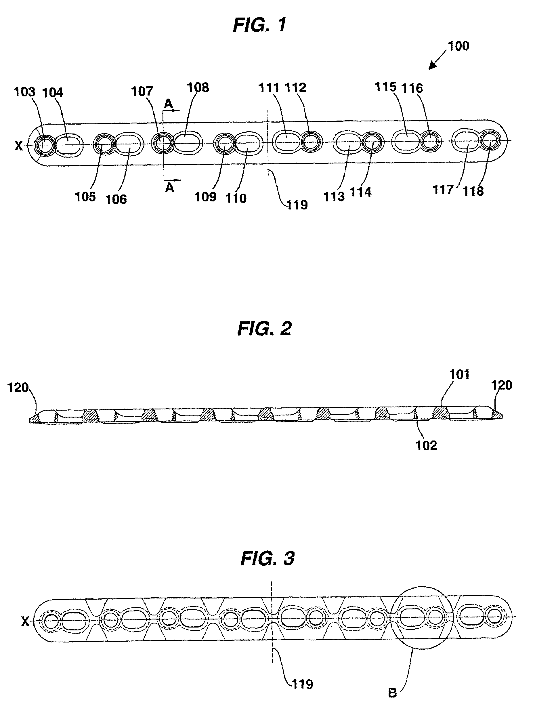
[0017]According to a particular embodiment of the invention, when there is more than one pair of holes, the threads of the holes intended to receive the plate fixation screws are inclined in an alternated manner, and can be interpolated or followed by a thread that is perpendicular to the plate. That is, a first hole intended to receive the plate fixation screw can be at a first inclination in relation to the perpendicular axis of the plate, a second hole intended to receive the plate fixation screw can be at an opposing inclination in relation to the perpendicular axis of the plate, and a third hole can be centered perpendicularly in relation to the perpendicular axis of the plate, and henceforth. The inclination sequence of the holes may vary, as long as it is alternated. This characteristic confers a better anchoring of the plate on the bone, since the forces exerted in the fixation of the plate are distributed in many points on the bone, and not only along the longitudinal axis of the plate. The distribution of forces along the bone becomes more balanced, therefore avoiding that the bone splits when the bone plate is fixated, besides reinforcing the anchoring of the bone on the plate.
[0019]The thread of the holes intended to receive the plate fixation screws, according to a particular embodiment of the invention, has a hyperbolic transversal profile. This configuration of the thread allows a better contact between the thread fillets on the hole and the thread fillets on the screw, hence avoiding stripping the screw when it is fastened. Likewise, the plate fixation screw shall comprise on its head a corresponding thread with a hyperbolic shape. The diameter of the hole and the pitch of the thread may also vary depending on the size of the plate and its application.
[0021]According to another particular embodiment of the invention, the bone plate can also eliminate the borders in its ends. This characteristic is highly advantageous when one wishes to fixate a fracture that occurred on the end of a bone. This is because the borders of the prior art plates makes difficult the insertion of the bone screw, and may also interfere in the joint near the bone.

Problems solved by technology

However, this type of fixation has the inconvenience of not being suitable for relatively thin plates, e.g. plates having with less than 2 mm of thickness.
Moreover, this plate does not allow an angular adjustment of the screws, both for the bone screw and for the screw for fixation of the plate, which can be extremely deficient for the plate anchoring, depending on the type of the fracture of the bone.
Although this type of plate solves the problem of the limitation of the thickness of the plate, it still has the inconvenient of not allowing an angular fixation of the screws to fix the plate on the bone.
Despite of solving the problem of the angling of the bone screws, the thread for placing the fixation screw does not follow the whole perimeter of the hole, which prevents good fixation of the screw, besides increasing the risk of stripping when fastened.
Moreover, this type of bone plate does not allow the angling of the plate fixation screw, which limits the anchoring of the bone plate.
Despite helping in plate fixation, the conical thread does not allow a good contact between the fillet of the thread and the screw, which can strip the thread when the screw is fastened.
This is extremely costly, since it forces, at the time of the surgery, the removal of the plate already inserted for the insertion of a new plate.
In addition, the plates of the prior art normally present a bead in their ends.
This is not advantageous when the fracture occurs in or near the end of the bone, since it prevents efficient fixation with the insertion of a bone screw, besides possibly interfering in the joint near the end of the bone.

Method used


Image

  • Bone Plate
  • Bone Plate
  • Bone Plate

Examples


Embodiment Construction

[0014]The above-mentioned objectives, among others, are achieved with the present invention, which consists in a bone plate that has an upper plane, intended to receive at least one bone screw and at least one fixation screw, and a lower plane, intended to support itself on a bone, in which said plate comprises at least one pair of holes laid out along at least one plane of the plate, wherein said pair of holes consists of a first hole intended to receive said at least one bone screw, and a second hole with a thread intended to receive said at least one fixation screw, characterized in that the holes of the pair are tangent to each other and separated between their centers at a distance at least equal to the sum of the radiuses of said holes, and in that the thread of at least one hole intended to receive a fixation screw is positioned at an angle in relation to a perpendicular axis of said plate.

[0015]Hence, according to a first aspect of the invention, the bone plate comprises the...


PUM


Abstract

The present invention refers to a bone plate for the osteosynthesis of a fractured bone. According to an embodiment of the present invention, the bone plate comprises an upper side (101), intended to receive at least one bone screw and at least one fixation screw, and a lower side (102), intended to support itself on the bone, wherein said plate further comprises at least one pair (122) of holes (115, 116) distributed along a plane of the plate, and given that said pairs of holes (115, 116) consist of a first hole (115) intended to receive at least one bone screw, and a second hole (116) that has a thread, intended to receive at least one plate fixation screw, wherein said holes that comprise the pair (122) are tangent to each other and separated between their centers at a distance at least equal to the sum of the radiuses of said holes.

Description

FIELD OF THE INVENTION[0001]The present invention generally refers to a bone plate for the osteosynthesis of a fractured bone.[0002]More specifically, the present invention refers to a bone plate for the osteosynthesis of a fractured bone through which it is possible to accomplish a better fixation and anchoring of said bone plate, in comparison to the known plates of the prior art.[0003]For the present specification, the terms “bone plate” or “plate for a bone” are employed indistinctly to designate a plate for the osteosynthesis of a fractured bone.BACKGROUND OF THE INVENTION[0004]The prior art discloses various embodiments of bone plates intended for the osteosynthesis of a fractured bone. These plates may assume varied shapes, depending on the bone and type of fracture in which they are employed. However, in general, they have a flat shape with two sides and a series of holes in their surface, for the insertion of one or more bone screws, used for the fixation of the fracture, a...

Claims


Application Information

Patent Timeline
IPC IPC(8): A61B17/70
CPCA61B17/8047
Inventor REIS, JR., GERALDO MARINS DOS
Owner GM DOS REIS JR INDA E COMERCIO DE EQUIPAMENTOS MEDICOS
Learn More