
Currency bill sensor arrangement

a technology of currency bill and sensor, which is applied in the field of currency bill processing system, can solve the problems of becoming ever more difficult to produce a device that can efficiently process a large number of mixed denomination and mixed series of currency bills

Active Publication Date: 2009-01-22
CUMMINS-ALLISON CORP
View PDF100 Cites 150 Cited by
  • Summary
  • Abstract
  • Description
  • Claims
  • Application Information

AI Technical Summary

Benefits of technology

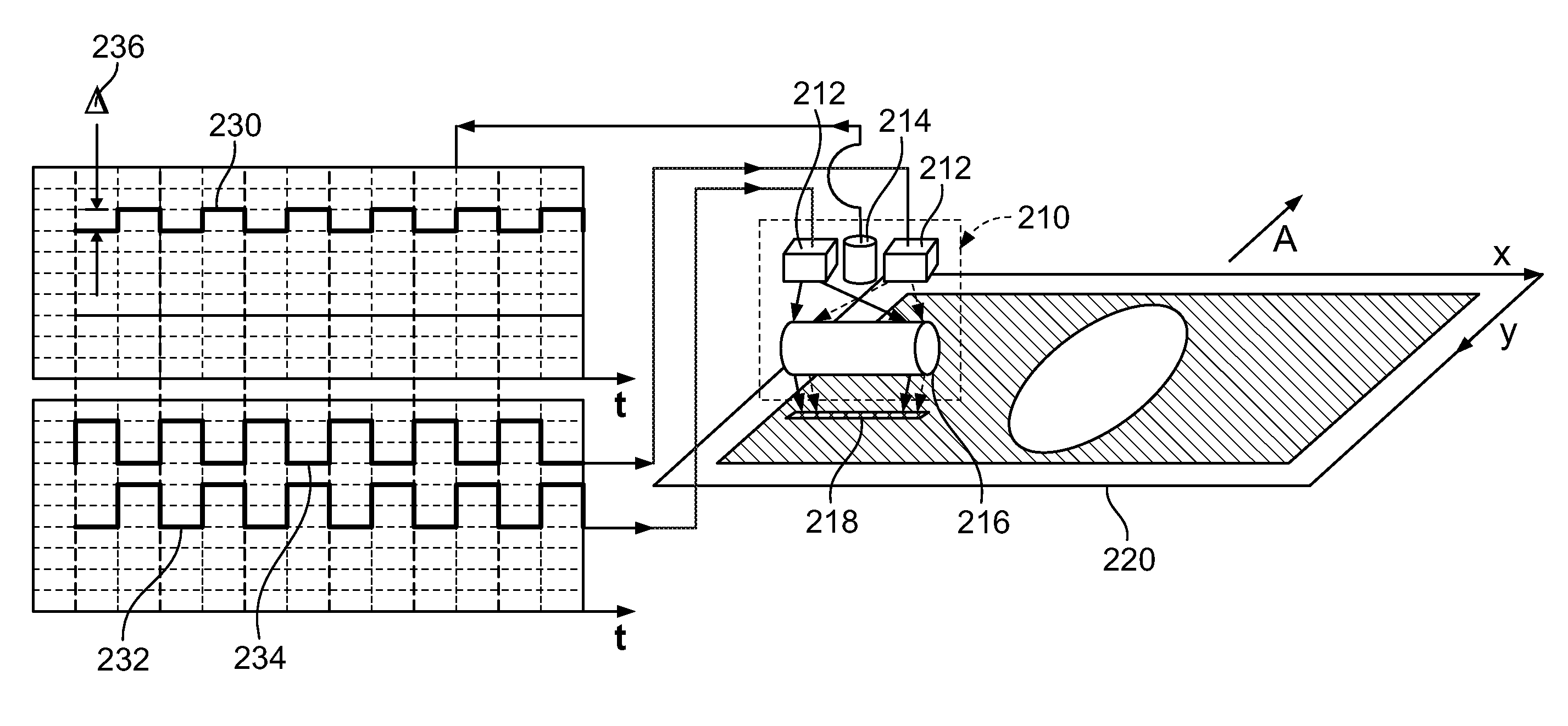
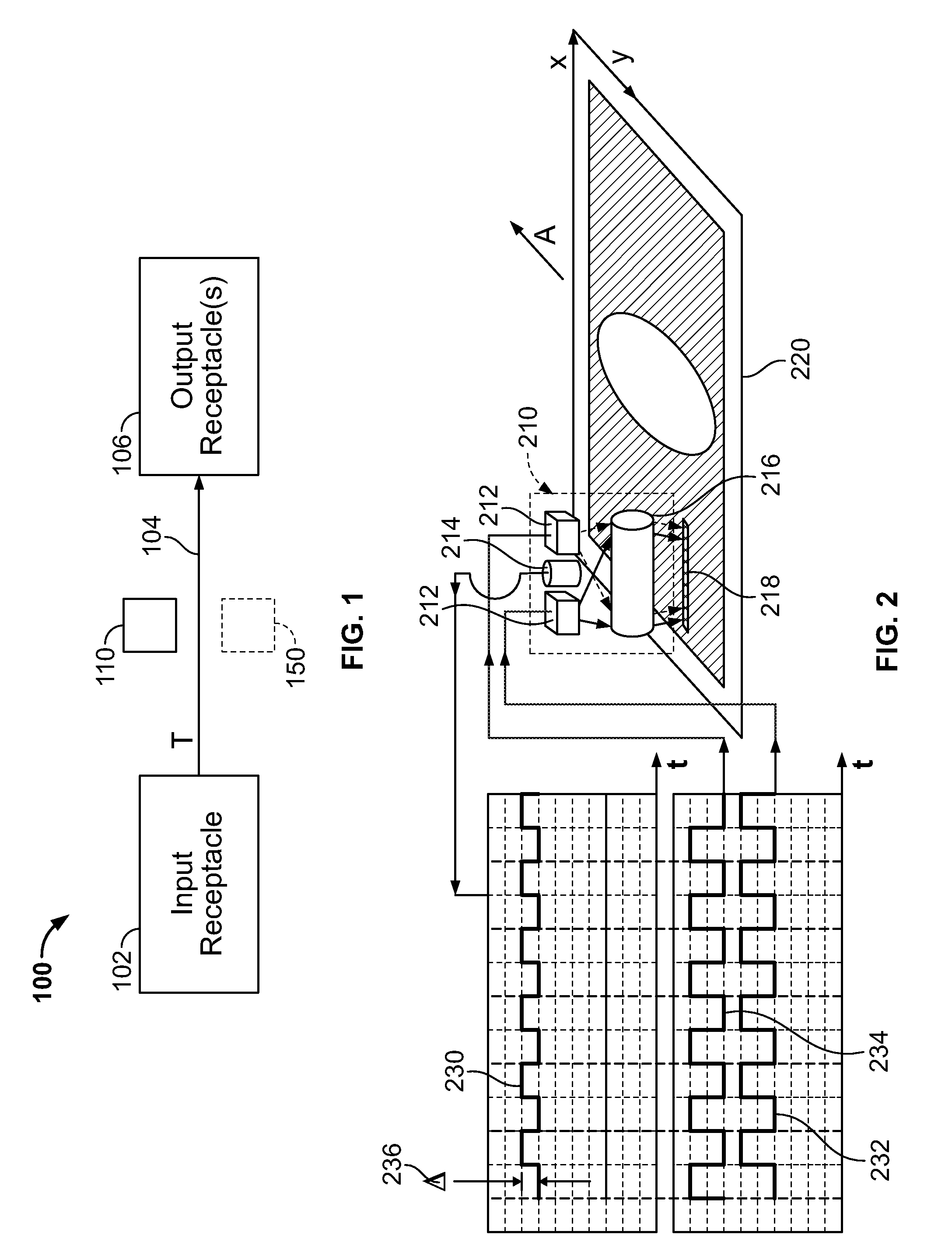
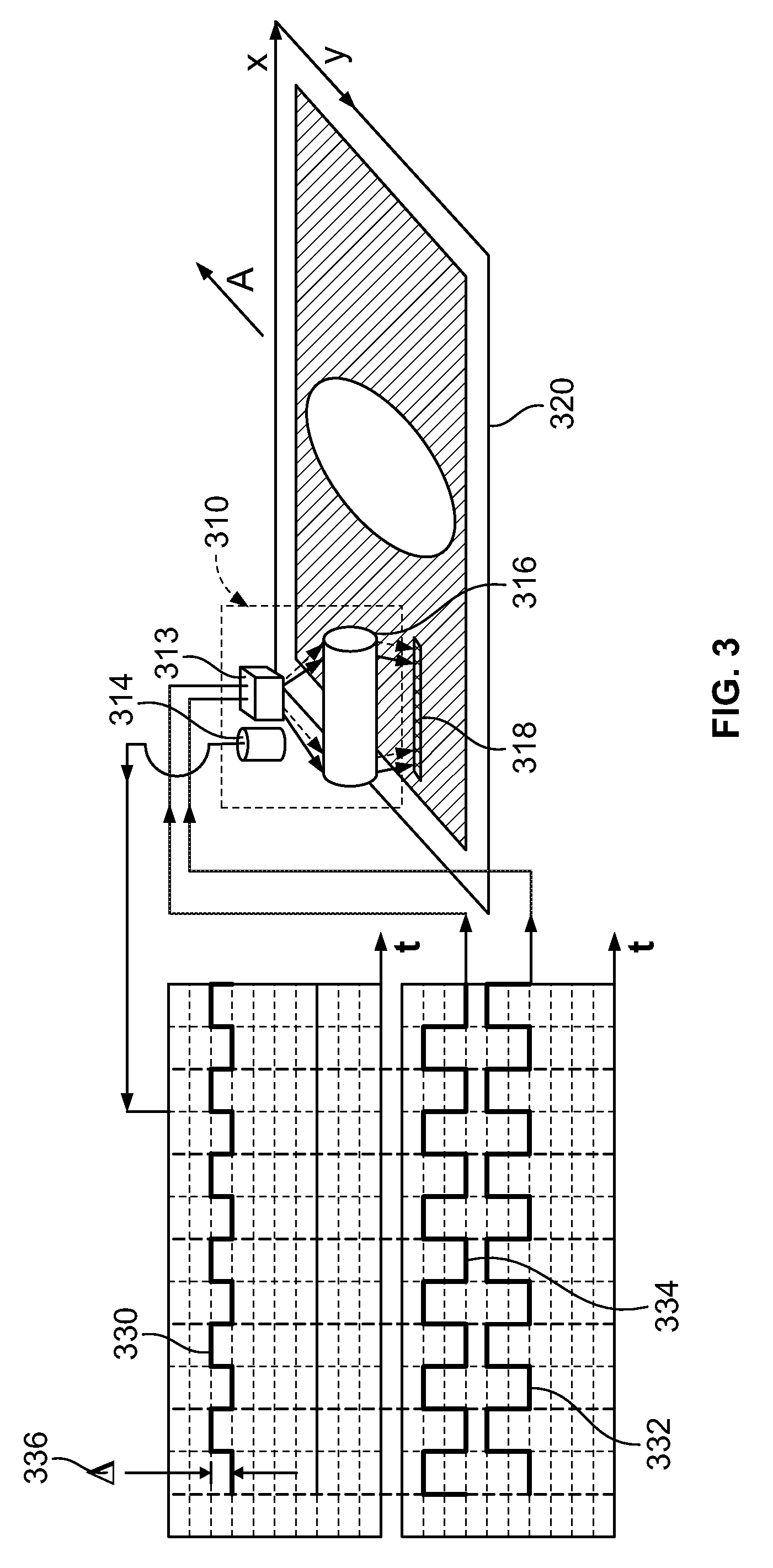
[0005]According to some embodiments, a currency processing device including a currency bill sensor arrangement is provided. The sensor arrangement utilizes one or more optical wavelengths, scans a banknote, and generates an electrical signal indicative of characteristics of the banknote. The electrical signal is processed and several sub-signals are obtained from the original electrical signal. A first sub-signal is an intensity signal which can be used for banknote processing, such as for denomination and / or authentication of the banknote by matching the obtained signal to a known master template and / or master data. A second sub-signal is an optical intensity difference of two or more wavelengths. Throughout the disclosure, this intensity difference can also be referred to as a difference signal, a reflectance difference, or Δ. The reflectance difference (Δ) can be used also to denominate by matching and / or comparing the reflectance difference (Δ) to a known template and / or master data or otherwise making a judgment using the reflectance difference and / or master data. In addition, Δ can be used to indicate a face orientation of a banknote (e.g., face up or face down), and / or to identify a series of a banknote, among other aspects.

Problems solved by technology

Thus, producing a device that can efficiently process a high number of mixed denomination and mixed series of currency bills is becoming ever more difficult.

Method used


Image

  • Currency bill sensor arrangement
  • Currency bill sensor arrangement
  • Currency bill sensor arrangement

Examples


embodiment a

Alternative Embodiment A

[0112]Embodiment A1: According to some embodiments, a sensor system consisting of multiple light emitting diodes (LEDs) and a rod lens a photo-detector and analog and digital electronics.

[0113]Embodiment A2: The sensor according to embodiment A1 using one multi-wavelength LED instead of multiple LEDs.

[0114]Embodiment A3: The sensor according to embodiment A1 that is used for banknote denomination.

[0115]Embodiment A4: The sensor according to embodiment A1 that is used for banknote or document authentication.

[0116]Embodiment A5: The sensor according to embodiment A1 that is used for banknote or document edge detecting.

[0117]Embodiment A6: The sensor according to embodiment A1 that is used for banknote or document print edge detecting.

[0118]Embodiment A7: The sensor according to embodiment A1 that uses two or more light wavelengths, detects the difference in reflectance between the two wavelengths to determine the incident side of the banknote.

[0119]Embodiment A...

embodiment b

Alternative Embodiment B

[0122]Embodiment B1: According to some embodiments, a sensor system consisting of one or more LED or a laser diode (LD) used as an excitation source, a rod lens and a photo-detector, a rectangular slab waveguide, and analog and digital electronics.

[0123]Embodiment B2: The sensor according to embodiment B1 that illuminates fibers embedded inside a banknote or a security document with a visible light from LED or LD, and detects infrared emission from the fibers.

[0124]Embodiment B3: The sensor according to embodiment B1 that utilizes Y-junction waveguide splitter.

embodiment c

Alternative Embodiment C

[0125]Embodiment C1: According to some embodiments, a sensor system consisting of one or more LED or a laser diode (LD) used as excitation source, a rod lens and a photo-detector, an optical filter, and analog and digital electronics.

[0126]Embodiment C2: The sensor according to embodiment C1 that illuminates fibers embedded inside a banknote or a security document with a visible light from LED or LD, and detects infrared emission from the fibers.


PUM


Abstract

A currency processing device for receiving a stack of U.S. currency bills and rapidly processing all the bills in the stack, the device comprising: an input receptacle adapted to receive a stack of U.S. currency bills of a plurality of denominations, the currency bills having a wide dimension and a narrow dimension; a transport mechanism positioned to transport the bills, one at a time, in a transport direction from the input receptacle along a transport path at a rate of at least about 1000 bills per minute with the narrow dimension of the bills parallel to the transport direction; a currency bill sensor arrangement positioned along the transport path, the currency bill sensor comprising: i) a multi-wavelength light source configured to emit a first wavelength of light and a second wavelength of light; ii) a cylindrical lens positioned to receive the first and second wavelengths of light from the multi-wavelength light source, the cylindrical lens illuminating an elongated strip of light on a surface of one of the plurality of currency bills, the cylindrical lens being configured to receive light reflected from the surface of the one of the plurality of currency bills; iii) a photodetector positioned to receive the reflected light, the photodetector generating an electrical signal in response to the received reflected light; iv) a processor configured to receive the electrical signal generated by the photodetector; wherein, the processor is configured to determine whether the surface of the one of the plurality of currency bills is a primary surface or a secondary surface based on the electrical signal.

Description

CROSS REFERENCE TO RELATED APPLICATIONS[0001]This application claims the benefit of U.S. Provisional Application No. 60 / 950,263, filed Jul. 17, 2007, which is incorporated herein by reference in its entirety.FIELD OF THE INVENTION[0002]The present disclosure relates generally to currency processing systems, and more particularly, to currency processing systems including a currency bill sensor arrangement.BACKGROUND OF THE INVENTION[0003]Currency processing devices typically include an input receptacle, a transport mechanism, a sensor, and an output receptacle. As currency bills are transported along a transport path, the sensor senses at least one characteristic associated with the transported currency bills. The currency processing devices typically compare information associated with the sensed characteristic to master data in order to make a judgment about a currency bill. As the number of different types (e.g., denominations, series, etc.) of currency bills increases, the size o...

Claims


Application Information

Patent Timeline
Patent Type & Authority Applications(United States)
IPC IPC(8): G06K9/00
CPCG07D11/0084G07D7/121G07D11/50
Inventor YACOUBIAN, ARAZJAGIELINSKI, TOMASZ M.
Owner CUMMINS-ALLISON CORP
Learn More