
X-ray diagnostic apparatus

a diagnostic apparatus and x-ray technology, applied in the field of x-ray diagnostic equipment, can solve the problems of renal failure, difficult to see the image of the catheter or guide wire, and the inability to see the blood vessel in the x-ray image, so as to improve the visibility of the image

Active Publication Date: 2009-01-22
TOSHIBA MEDICAL SYST CORP
View PDF1 Cites 27 Cited by
  • Summary
  • Abstract
  • Description
  • Claims
  • Application Information

AI Technical Summary

Benefits of technology

[0007]It is an object of the present invention to improve the visibility of an image of a catheter or guide wire.

Problems solved by technology

However, the blood vessel cannot be seen in an X-ray image unless enhanced by a contrast medium.
Keeping injecting the contrast medium to visualize the blood vessel may result in renal failure.
This makes it very difficult to see the image of the catheter or guide wire.

Method used


Image

  • X-ray diagnostic apparatus
  • X-ray diagnostic apparatus
  • X-ray diagnostic apparatus

Examples


Embodiment Construction

[0016]An embodiment of the present invention will be described below with reference to the views of the accompanying drawing.

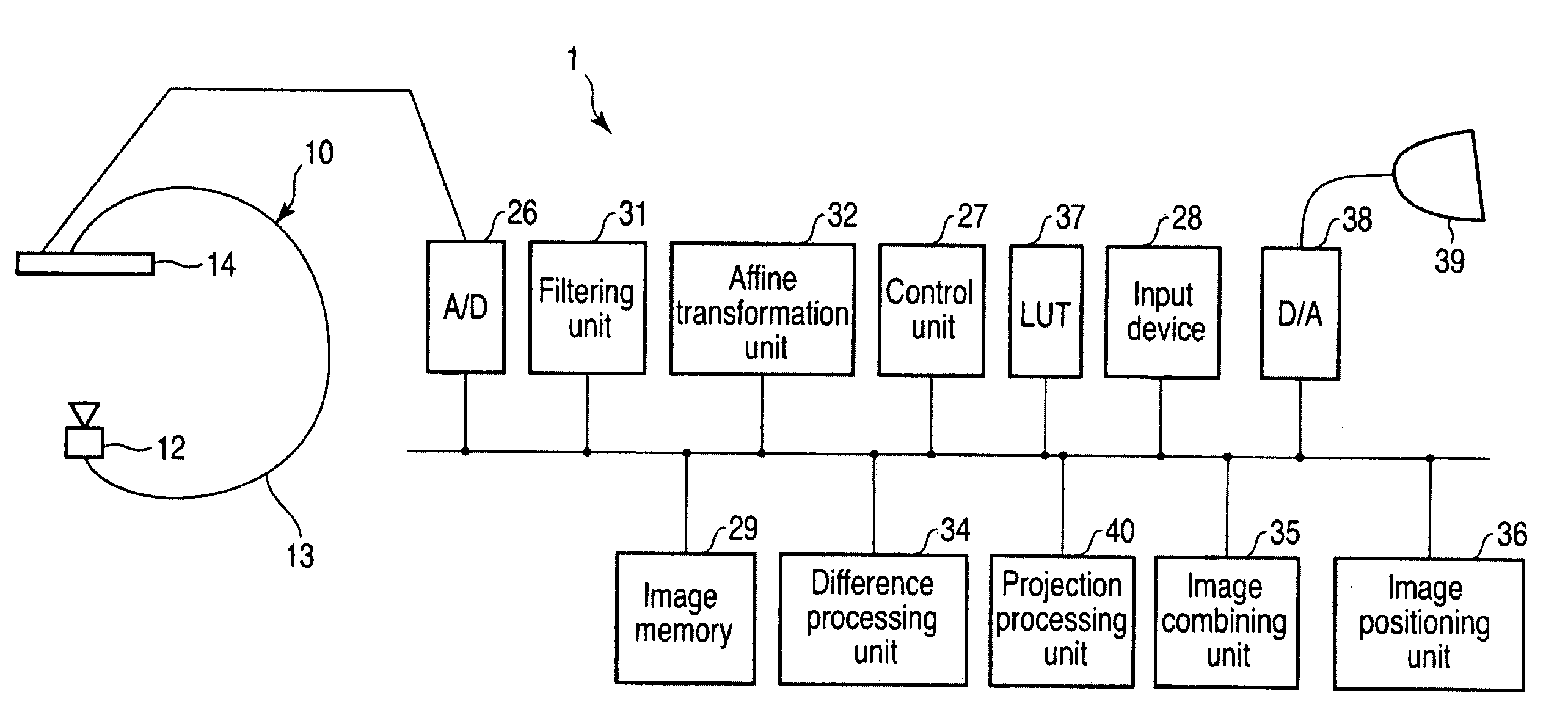
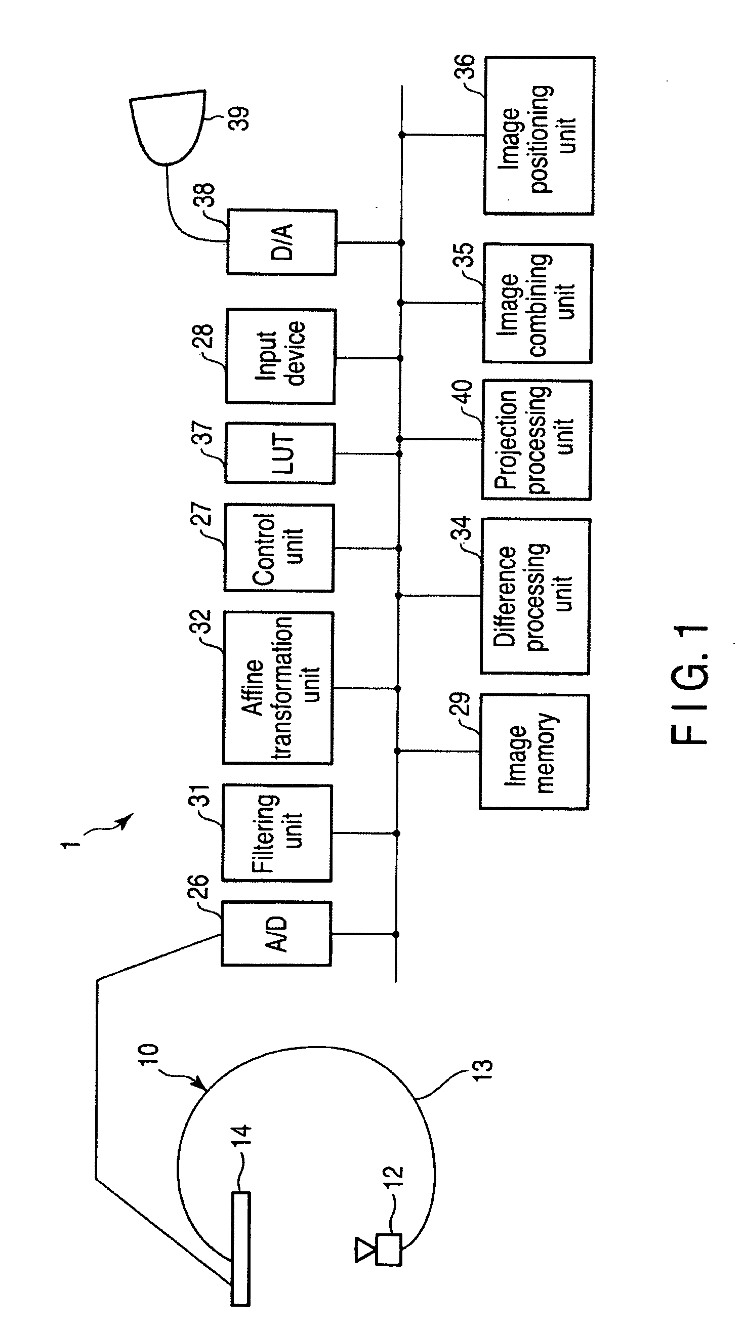
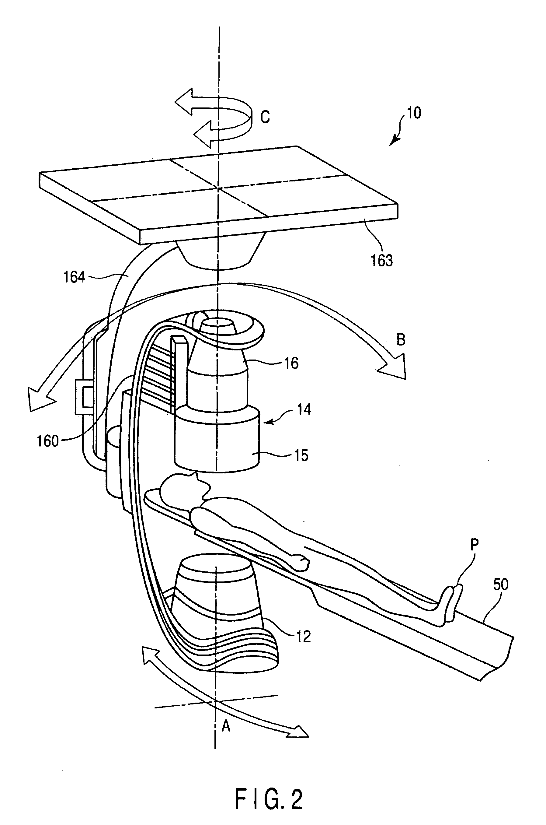
[0017]As shown in FIG. 1, an X-ray diagnostic apparatus includes an X-ray imaging mechanism 10 and an image processing apparatus 1. As shown in FIG. 2, the X-ray imaging mechanism 10 includes an X-ray tube 12 and an X-ray detector 14. The X-ray detector 14 comprises a combination of an image intensifier 15 and a TV camera 16. The X-ray detector 14 may comprise a flat panel detector (FPD) having a plurality of semiconductor detection elements arrayed in a matrix form instead of the combination of the image intensifier 15 and the TV camera 16. The X-ray tube 12 is mounted on one end of a C-arm 160. The X-ray detector 14 is mounted on the other end of the C-arm 160 in a direction to face the X-ray tube 12. A subject P on a top 50 of a bed is placed between the X-ray tube 12 and the X-ray detector 14. The C-arm 160 is supported by, for example, a arcuated column 1...


PUM


Abstract

An X-ray diagnostic apparatus comprises an X-ray image generating unit which generates a series of a plurality of X-ray images associated with a subject to be examined, a storage unit which stores data of a three-dimensional image associated with the subject, an image processing unit which generates data of a two-dimensional blood vessel image from the stored data of the three-dimensional image, a difference processing unit which generates a plurality of difference images by subtracting the X-ray images from each other, and a display unit which superimposes and displays each of the plurality of difference images and the two-dimensional blood vessel image.

Description

CROSS-REFERENCE TO RELATED APPLICATIONS[0001]This application is based upon and claims the benefit of priority from prior Japanese Patent Application No. 2007-187427, filed Jul. 18, 2007, the entire contents of which are incorporated herein by reference.BACKGROUND OF THE INVENTION[0002]1. Field of the Invention[0003]The present invention relates to an X-ray diagnostic apparatus which displays a road map representing a blood vessel structure.[0004]2. Description of the Related Art[0005]In intervention or angiographic examination, a catheter is inserted into a blood vessel from, for example, the joint of a leg and is brought to a target region through the blood vessel. This catheter or a guide wire inserted in the catheter is moved forward to a target position under fluoroscopic observation of an X-ray image. However, the blood vessel cannot be seen in an X-ray image unless enhanced by a contrast medium. Keeping injecting the contrast medium to visualize the blood vessel may result in...

Claims


Application Information

Patent Timeline
Patent Type & Authority Applications(United States)
IPC IPC(8): A61N5/10
CPCA61B6/12A61B6/504A61B6/481A61B6/463
Inventor OHISHI, SATORU
Owner TOSHIBA MEDICAL SYST CORP
Learn More