Eureka AIR delivers breakthrough ideas for toughest innovation challenges, trusted by R&D personnel around the world.

Apparatus for the Control of Lighting and Associated Methods

a technology of semiconductors and lighting, applied in the direction of electric variable regulation, process and machine control, instruments, etc., can solve the problems of difficult to predict the intensity of led lights, difficult to provide intensity control of lighting, and difficult to control voltage, so as to reduce heat dissipation, reduce the effect of heat dissipation and smooth outpu

Active Publication Date: 2009-01-22
GARDASOFT VISION
View PDF8 Cites 18 Cited by
  • Summary
  • Abstract
  • Description
  • Claims
  • Application Information

AI Technical Summary

Benefits of technology

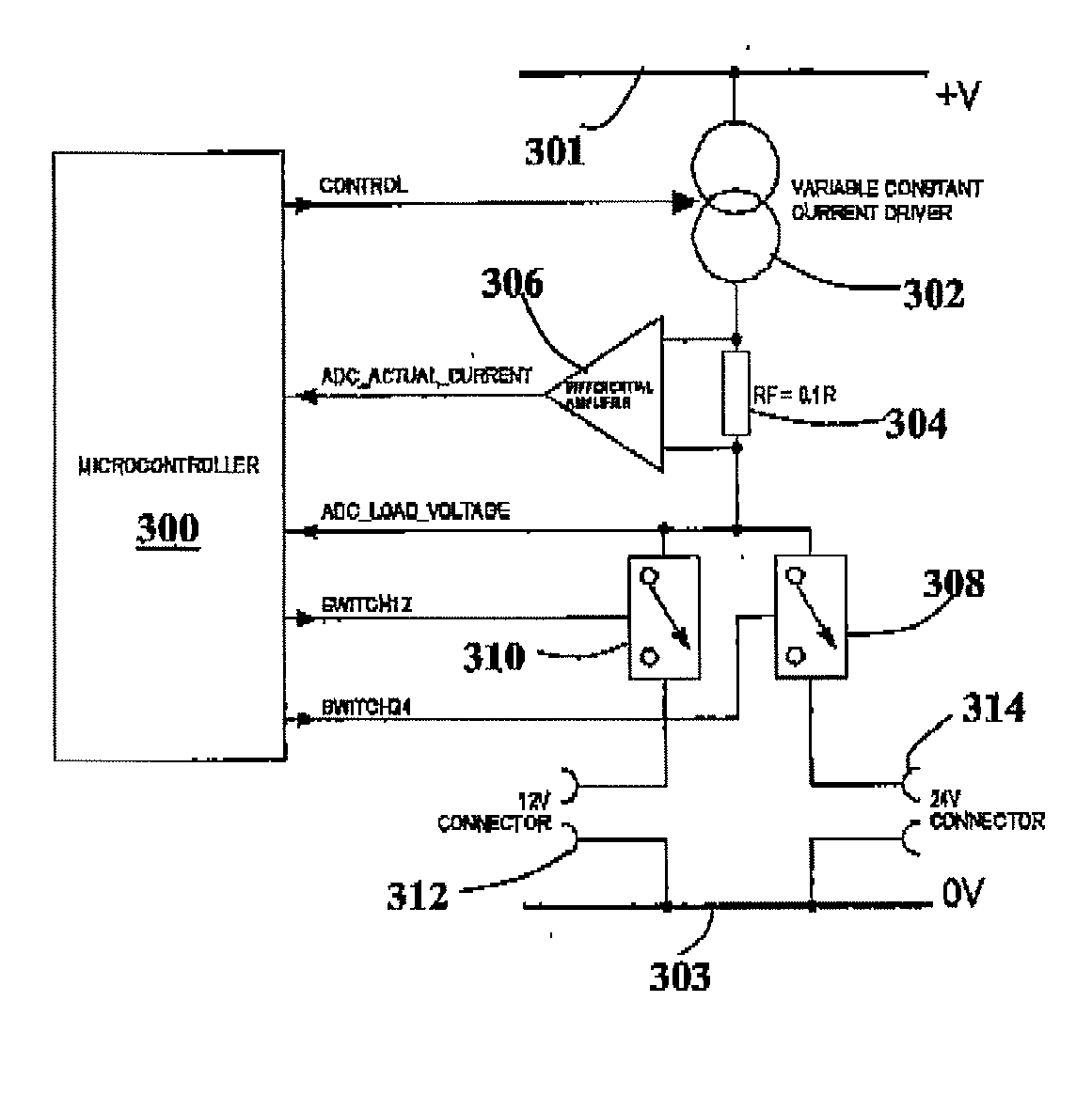
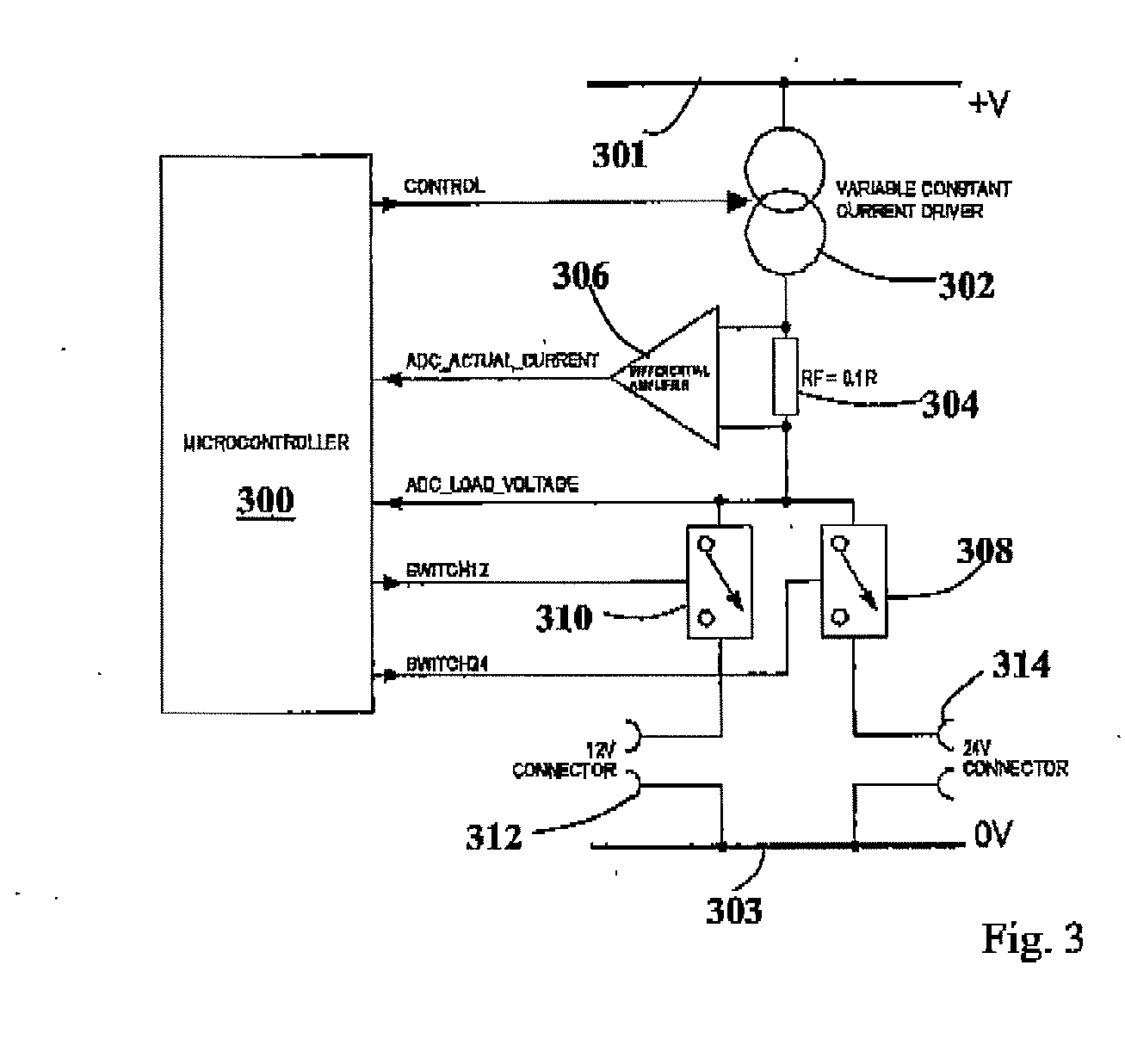
[0010]An advantage of such an invention is that it drives the LED's with a constant current rather than a voltage and thus many of the problems associated with the prior art may be reduced or overcome. Further, stepping up the initial current is advantageous because it helps to allow an LED to be correctly driven once connected to the controller without damage thereto.
[0051]The controller may be arranged to monitor the voltage across the analogue regulation and may be further arranged to adjust the output voltage of any switch mode power supply or voltage converter to keep the voltage across the analogue regulation at a low and approximately constant value. Such an arrangement tends to reduce the heat dissipation through the analogue regulation, allowing more efficient use of power, lower running temperature, smaller components or less heatsink to be required.

Problems solved by technology

However there are problems with such voltage control.
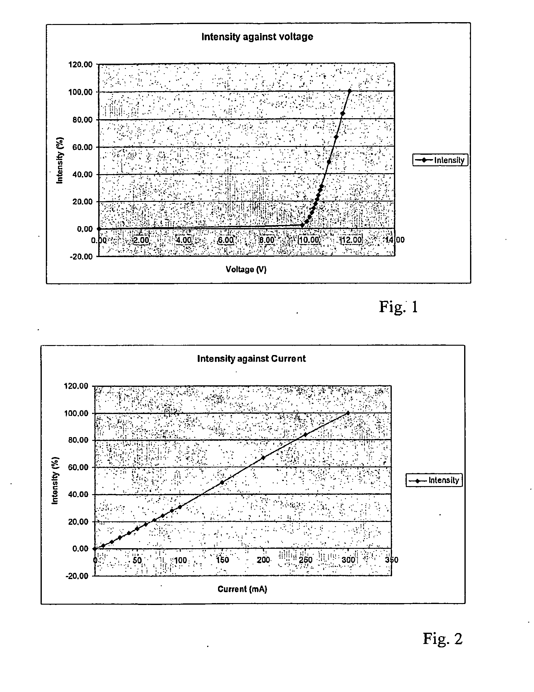
It is difficult to provide intensity control of lighting when driving it using a voltage supply, because it is difficult to predict what the LED intensity will be at any voltage.
There may be problems with the forward voltage specifications of LED's, particularly white LED's.
However, a low forward voltage can be a problem in LED lighting because it means that if a voltage supply is used, the current flowing through the LED's increases resulting in reducing lifetime.

Method used


Image

  • Apparatus for the Control of Lighting and Associated Methods
  • Apparatus for the Control of Lighting and Associated Methods
  • Apparatus for the Control of Lighting and Associated Methods

Examples


Embodiment Construction

/ / ********************************************************************** / / / / Function:CurrentSense / / / / Parameters:pfCurrentRating / / pfVoltageRating / / / / Result:TRUE if current sensing is successful / / / / Assumes that a lighting unit is connected. / / / / Detect whether the lighting unit is rated at 12V or 24V / / / / Start at 10mA and increase the current until the voltage / / across the lighting unit reaches the rated voltage. The current / / needed to do this is the current rating for the lighting. / / / / The lights are pulsed for a short time to ensure that an / / abnormal condition does not cause the lights to be damaged / / / / Detected fault conditions: / / There is no light connected / / The lighting unit is short circuit / / The lighting unit requires too much current / / The current flowing is not the expected current / / / / **********************************************************************#defineSENSE_MIN_CURRENT(0.01F) / / Minimum current sensed inamps#defineSENSE_MAX_CURRENT(0.5F) / / Maximum allowed currentin ...


PUM


Abstract

A lighting controller arranged to drive one or more light emitting semiconductors, the controller comprising a current source and / or a voltage source and a current and / or voltage sensor wherein the controller is arranged to drive the or each light emitting semiconductor using a substantially constant current or voltage and further arranged to either monitor the actual current passing through the light emitting semiconductor and the controller being arranged to monitor the voltage such that the disconnection or occurrence of faults within the or each light emitting semiconductor can be detected; or monitor the actual voltage across the light emitting semiconductor and the controller being arranged to monitor the current such that the disconnection or occurrence of faults within the or each light emitting semiconductor can be detected.

Description

FIELD OF THE INVENTION[0001]This invention relates to an apparatus for the control of light emitting semiconductors lighting and associated methods and in particular, but not exclusively, to LED lighting.BACKGROUND OF THE INVENTION[0002]It will be appreciated that forms of light emitting semiconductor, other than LED's, are available. It is however convenient to refer to LED's as the elements that provide light and in the following description reference to LED's should be taken to include light emitting semiconductors. LED'S are well known and with the advent of new LED's it is now possible to replace standard white light with LED equivalents. The longevity and cost saving advantages of this will be readily apparent to the person skilled in the art.[0003]It is known to control LED's using voltage control. However there are problems with such voltage control. For example, a small variation in voltage will result in a large variation in output intensity. For example a 0.1% change in i...

Claims


Application Information

Patent Timeline
IPC IPC(8): H05B37/02H05B44/00
CPCH05B33/0812H05B33/0887Y02B20/345Y02B20/343H05B33/0893H05B45/395H05B45/50H05B45/58Y02B20/30
Inventor BHAGAT, PETER
Owner GARDASOFT VISION
Why Eureka
Eureka Blog
Learn More