Actuator
- Summary
- Abstract
- Description
- Claims
- Application Information
AI Technical Summary
Benefits of technology
Problems solved by technology
Method used
Image

Examples
first exemplary embodiment
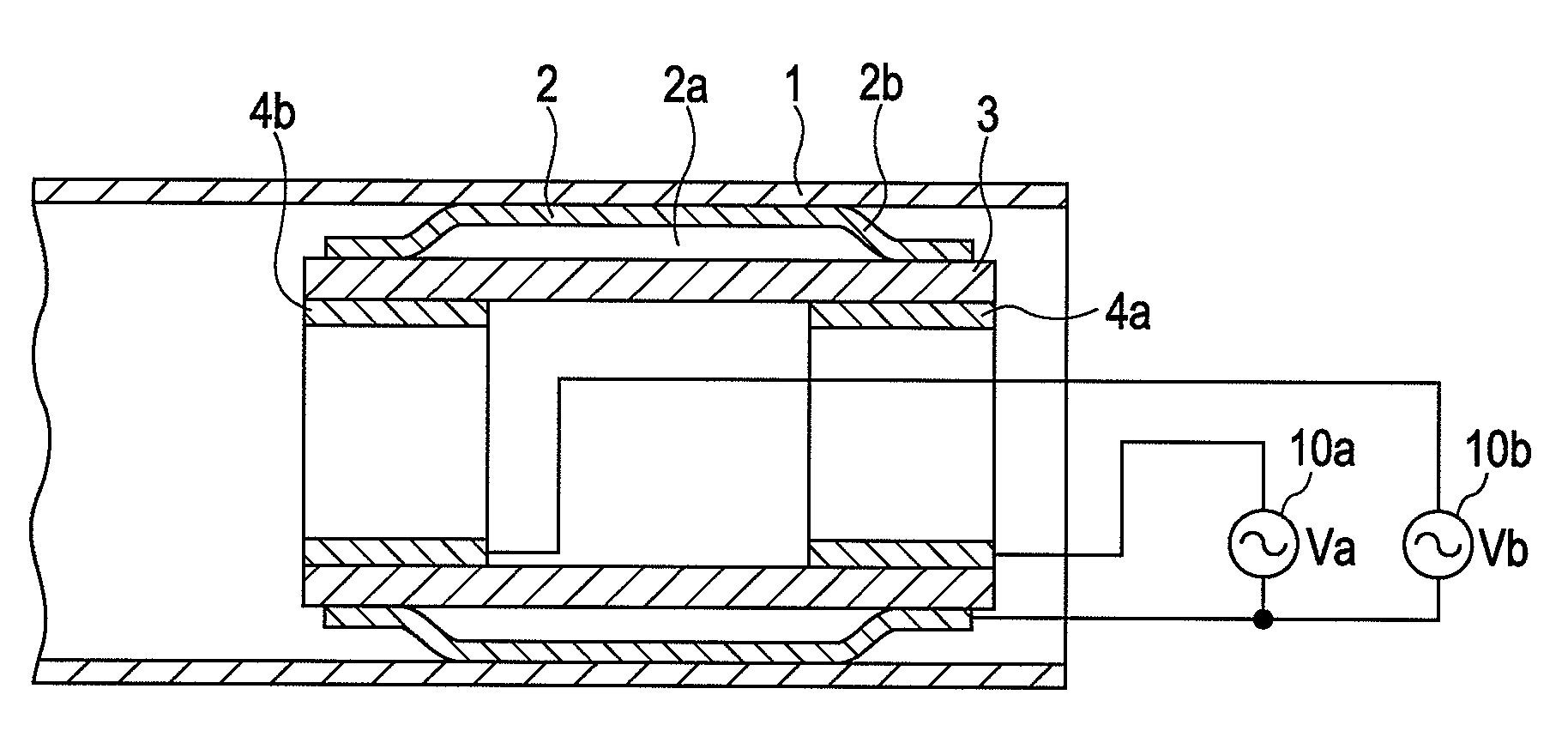
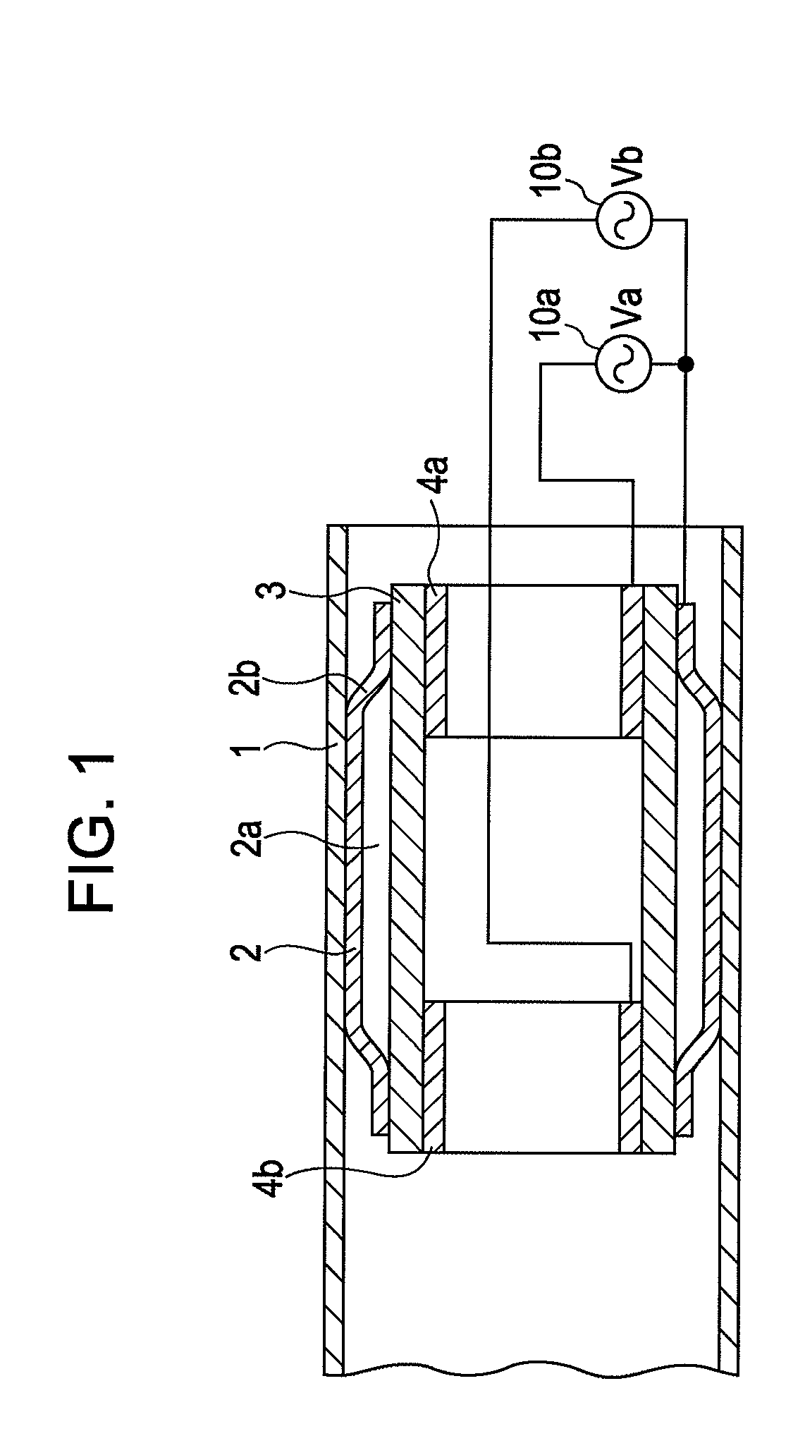
[0045]FIG. 1 shows an actuator according to a first exemplary embodiment of the present invention. A tubular member 1 is a cylindrical member functioning as a stator. A vibrator 2 is a cylindrical member. A diameter of an axial central portion of the vibrator 2 is larger than that of end portions thereof and the vibrator has a central-portion-swollen shape. This swollen portion is arranged to fit the tubular member 1. The vibrator 2 is formed of metal, such as stainless, or metal glass. A piezoelectric element 3 is a cylindrical member and is fixed to an inner surface of the vibrator 2 at both end portions. A gap 2a is formed between the central portion of the vibrator 2 and the piezoelectric element 3.
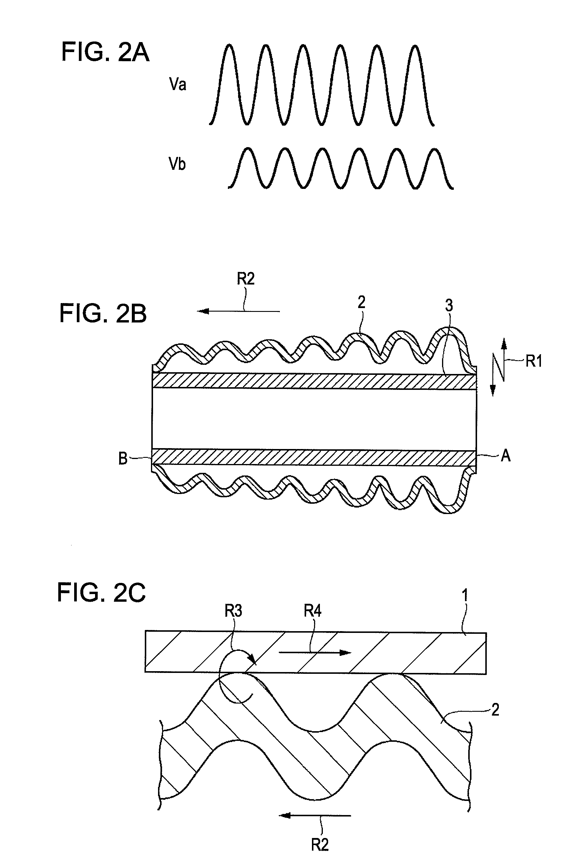
[0046]A first electrode (segmented electrode) 4a and a second electrode (segmented electrode) 4b are provided at the respective end portions of the inner surface of the piezoelectric element 3. Alternating power supplies 10a and 10b apply vibration voltages across the first electrode ...
modified example 1
[0066]Instead of using the vibrator 2 having minute holes formed thereon, holes 3a are formed on the piezoelectric element 3 in advance and may be filled with the same material as the sacrificial layer 12, as shown in FIG. 4A. By connecting the holes 3a provided on the piezoelectric element 3 to a passage to be connected to a refrigerant circulation pump 5, the refrigerant can be circulated through the gap 2a. If the piezoelectric element 3 is vibrated at a high speed and a large amplitude, an amount of generated heat increases. By introducing the refrigerant to the gap 2a between the piezoelectric element 3 and the vibrator 2, this heat can be removed. As a result, an increase in the temperature of the piezoelectric element 3 and the vibrator 2 can be suppressed.
modified example 2
[0067]The contact portion of the vibrator 2 and the tubular member 1 does not have to be flat. The vibrator 2 may be in the shape of a corrugated plate having a wave-shape portion 2c as shown in FIG. 4B. The vibrator 2 in the shape of the corrugated plate can be readily manufactured by forming netlike masking at the time of deposition of the sacrificial layer 12.
[0068]During vibration of the vibrator 2, the pressure of air existing between the vibrator 2 and the tubular member 1 levitates the vibrator 2. That is, so-called ultrasonic levitation is caused. However, since the corrugated plate of the vibrator 2 allows compressed air to escape from the grooves of the corrugated plate even if the air existing in the gap adjacent to the contact portion is compressed, the pressure does not increase. Accordingly, the levitation of the vibrator 2 can be prevented. As a result, the thrust does not reduce even if the vibrator 2 vibrates at a large amplitude.
PUM
 Abstract
Description
Claims
Application Information
 - R&D
- Intellectual Property
- Life Sciences
- Materials
- Tech Scout
- Unparalleled Data Quality
- Higher Quality Content
- 60% Fewer Hallucinations
Browse by: Latest US Patents, China's latest patents, Technical Efficacy Thesaurus, Application Domain, Technology Topic, Popular Technical Reports.
© 2025 PatSnap. All rights reserved.Legal|Privacy policy|Modern Slavery Act Transparency Statement|Sitemap|About US| Contact US: help@patsnap.com