
Apparatuses, methods and systems relating to automatic golf data collecting and recording

a golf data and automatic technology, applied in the field of golf games, can solve the problems of inconvenient golfers to press, delay in the game, and inability to drive a golf car

Inactive Publication Date: 2009-01-15
LEI CO LTD
View PDF50 Cites 164 Cited by
  • Summary
  • Abstract
  • Description
  • Claims
  • Application Information

AI Technical Summary

Benefits of technology

[0013]Apparatuses, methods and systems relating to automatic golf data collecting & recording are described herein. In one embodiment, RFID-enabled golf balls and golf clubs and sequences of events and rules allow for automatic recording of when and where a golf stroke occurs.
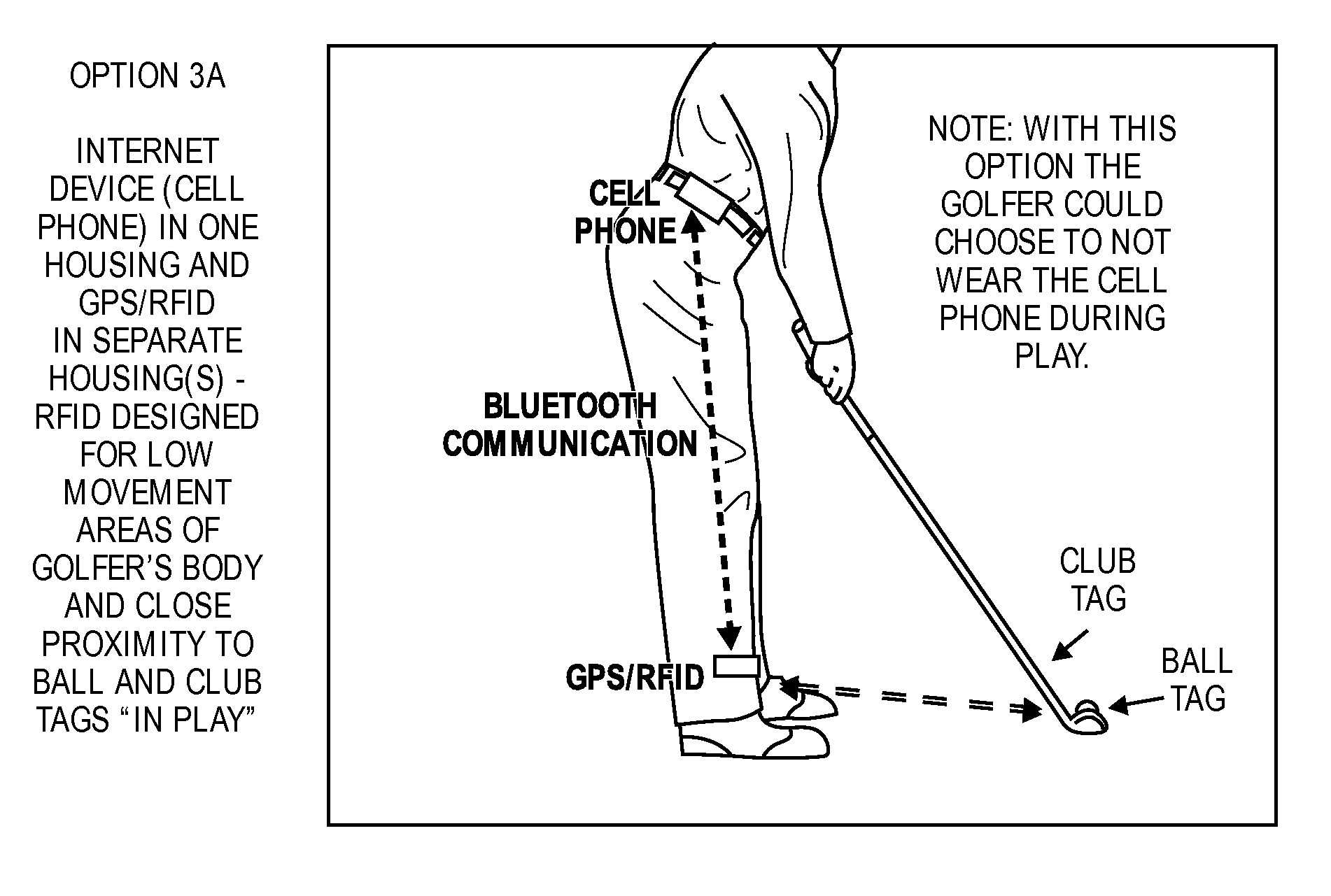
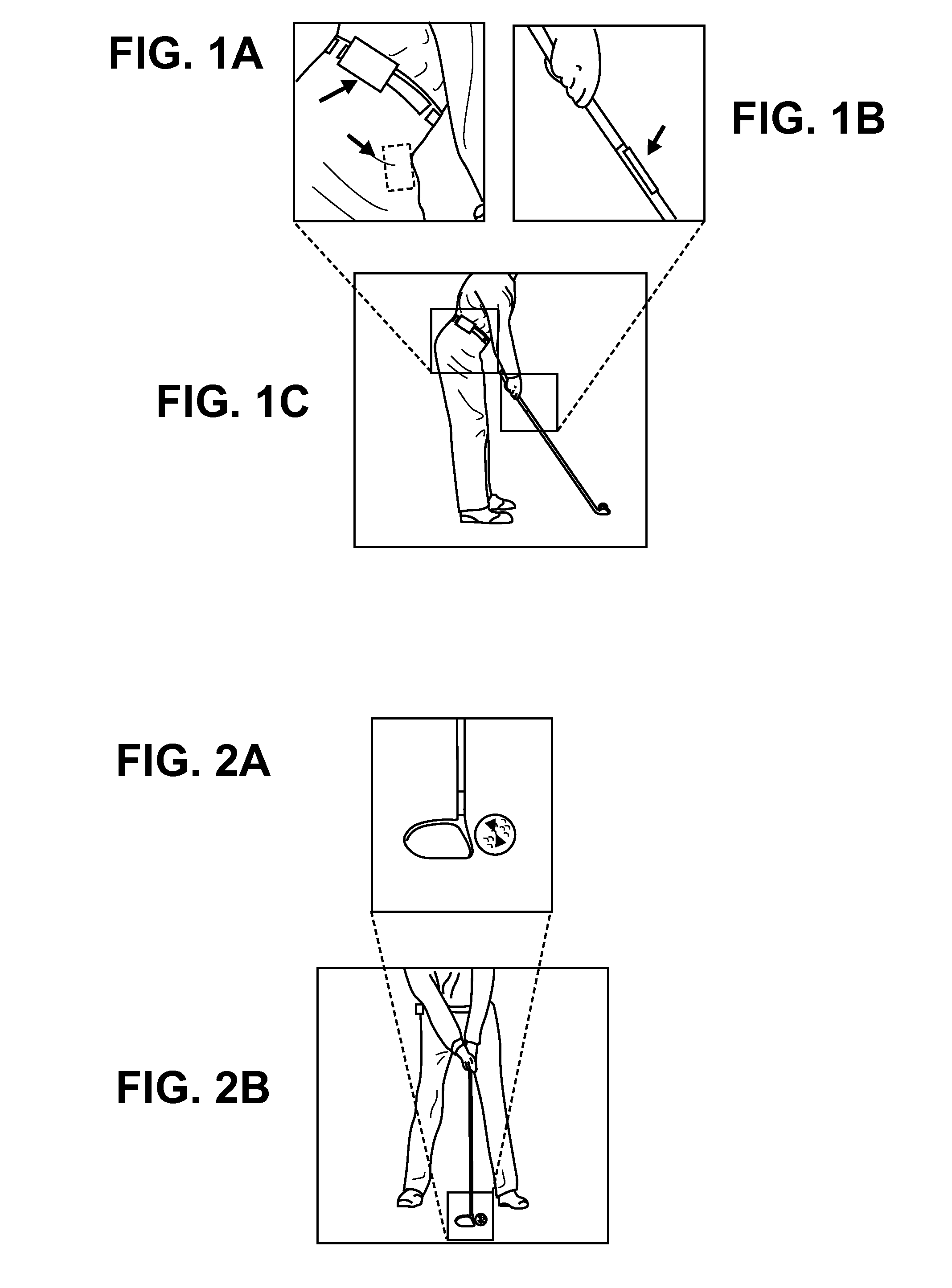
[0014]In one exemplary embodiment of an aspect of the invention, an integrated GPS device & RFID transceiver is used with passive RFID tagged golf balls and clubs and sequences of events and rules that enable accurate automatic golf data collection. Active tags may also be used in place of passive tags, but passive tags are preferable, in some embodiments, to reduce weight and need for power supply for the tags.
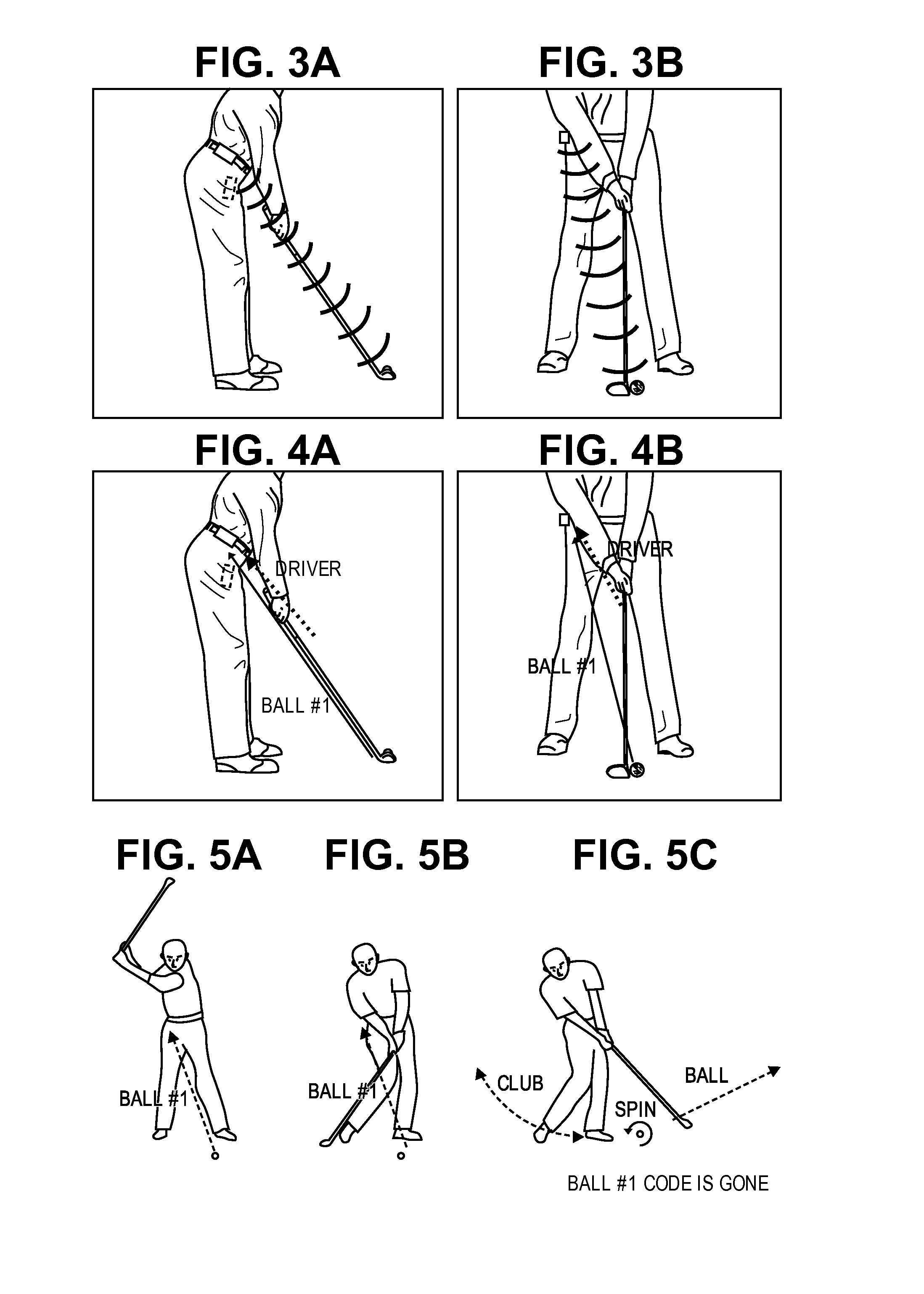
[0024]3. When #1 & #2 occur together over a period of time, the transceiver transmits / receives at an increased rate. Note: reducing the amount of time the transceiver is sending / receiving at an increased rate will conserve battery power.
[0029]Note: for putts there will be times when the ball code of the ball hit is still received after the putt is complete. The system can use a different protocol, described herein, for putting. For example, a stationary amplitude signal followed by a relatively slow amplitude and / or phase fluctuation indicates that a ball has moved from stationary to rolling. The system will know when a putter is being used because the putter's RFID tag in the putter identifies the putter to the RFID transceiver (and will know when the golfer is on the putting green because the GPS receiver's latitude / longitude will identify the location relative to a map of the current golf course). Operation 7 will likely be deleted from the protocol of recording a golf stroke for putting. It is possible to include a rule for putting that after Operation 2 has happened (still signals from ball) the system must detect a movement in the ball with diminishing signal strength (meaning the ball is moving away from the transceiver). This could possibly help avoid confusion if a golfer suddenly picked up a ball from the putting green (e.g. to clean it or mark it).

Problems solved by technology

Often golf carts are restricted to “cart path only” access on a golf course and it is often not practical to drive a golf cart to the actual location of a golf ball due to the terrain.
However golfers seldom use the features because the process of manually entering data is too labor intensive on a golf course and will lengthen the duration of each golf shot, causing delays in the game.
The problem with existing systems is golfers do not want to take action to record the data of each golf shot.
It is inconvenient for golfers to take the time to press buttons, select from drop-down lists, etc. to record information about every golf shot.
One could say it is impractical for golfers to do so.
Further, if golfers took the time to enter data in such a manual manner it would result in slower play which is not good for the golfers or the golf courses.
The problem of requiring the golfer to enter data manually is known.
The solutions taught by Reeves are impractical and fail to address all the issues required to accurately collect and record golf data.
Without a means of identifying and monitoring the golf ball the system taught by Reeves does not provide sufficient automation.
Further, Reeves teaches requiring expensive and sophisticated electronics on the golf club (i.e. battery, motion detector, and accelerometer).
The expense and bulkiness of such components make for an impractical solution.
The system disclosed seems to be problematic and potentially ineffective for several reasons.
Further, this patent, which bases the confirmation of a golf stroke by the sound made by the club striking the ball, has no means of knowing whether or not a ball was hit out of bounds or if the ball is lost.
A further potential problem relates to the insensitivity to a very gentle putt that generates no characteristic sound pattern.
Therefore the system does not automatically record golf data.

Method used


Image

  • Apparatuses, methods and systems relating to automatic golf data collecting and recording
  • Apparatuses, methods and systems relating to automatic golf data collecting and recording
  • Apparatuses, methods and systems relating to automatic golf data collecting and recording

Examples


Embodiment Construction

RFID Tagged Golf Balls

[0069]An important aspect of the present invention is the ability to equip golf balls with tags in such a way that the performance of the golf ball is not changed in any way. The golf ball should be conforming to the rules of golf (USGA and R&A) and have the same performance and durability as a non-tagged golf ball. U.S. patent application Ser. Nos. 10 / 672,365 (filed on Sep. 26, 2003), 10 / 672,600 (filed on Sep. 26, 2003), and 11 / 248,766 (filed on Oct. 11, 2005) describe such golf balls with tags and these applications are hereby incorporated herein in their entirety by reference.

[0070]The tag may be active or passive but should use the architecture described above in order to be a high performance golf ball with high durability and conformance to the rules of golf. In an exemplary embodiment the tag used in the present invention is a passive RFID tag. The passive RFID tag in the ball will consist of an antenna made of elastic conductive material and an electric...


PUM


Abstract

In one exemplary embodiment, an integrated GPS device & RFID transceiver is used with passive RFID tagged golf balls and clubs and sequences of events and rules that enable accurate automatic golf data collection. Active tags may also be used in place of passive tags.

Description

[0001]This application claims priority to U.S. Provisional Application No. 60 / 949,458, filed on Jul. 12, 2007.FIELD OF THE INVENTION[0002]The present invention relates to the game of golf or other games, and more particularly to an improved golf data collecting and recording system.BACKGROUND OF THE INVENTION[0003]GPS rangefinders are popular in the game of golf. GPS rangefinders are used to inform the golfer of the golfer's location on a golf course relative to the location of other mapped areas of interest on the course (e.g. sand traps, greens, etc.) GPS rangefinders are typically available in either cart-mounted or handheld versions.[0004]Examples of popular cart-mounted GPS rangefinder products include Prolink and UpLink. Examples of popular handheld GPS products include the SkyCaddie by SkyHawke and Golflogix, to name a few. A potentially valuable feature of handheld GPS rangefinders is the ability for the golfer to “mark the location” of the ball and other areas of interest. ...

Claims


Application Information

Patent Timeline
IPC IPC(8): A63B57/00G01C21/00A63B71/06
CPCA63B24/0021G01S13/758A63B69/0028A63B69/3614A63B69/3658A63B71/0605A63B71/0669A63B2024/0025A63B2024/0031A63B2024/0037A63B2071/0611A63B2071/0691A63B2220/12A63B2220/13A63B2220/14A63B2220/17A63B2220/20A63B2220/30A63B2220/35A63B2220/62A63B2220/836A63B2225/20A63B2225/50A63B2225/54A63B2243/0029G01S13/56A63B43/00A63B2024/0053A63B2220/803A63B2220/833A63B2220/89A63B2102/32
Inventor SAVARESE, CHRISMARSHALL, NOEL H. C.MCGILL, SUSAN
Owner LEI CO LTD
Learn More