
Anti-sink rim

a technology of anti-slip rims and rims, which is applied in the direction of auxillary traction increasing equipment, wheel attachments, multiple wheel assemblies, etc., can solve the problems of inability to prevent from one another, limited distance, and risks of injuries, and achieve the effect of increasing grip

Active Publication Date: 2009-01-15
BIESSE PHILIPPE
View PDF21 Cites 7 Cited by
  • Summary
  • Abstract
  • Description
  • Claims
  • Application Information

AI Technical Summary

Benefits of technology

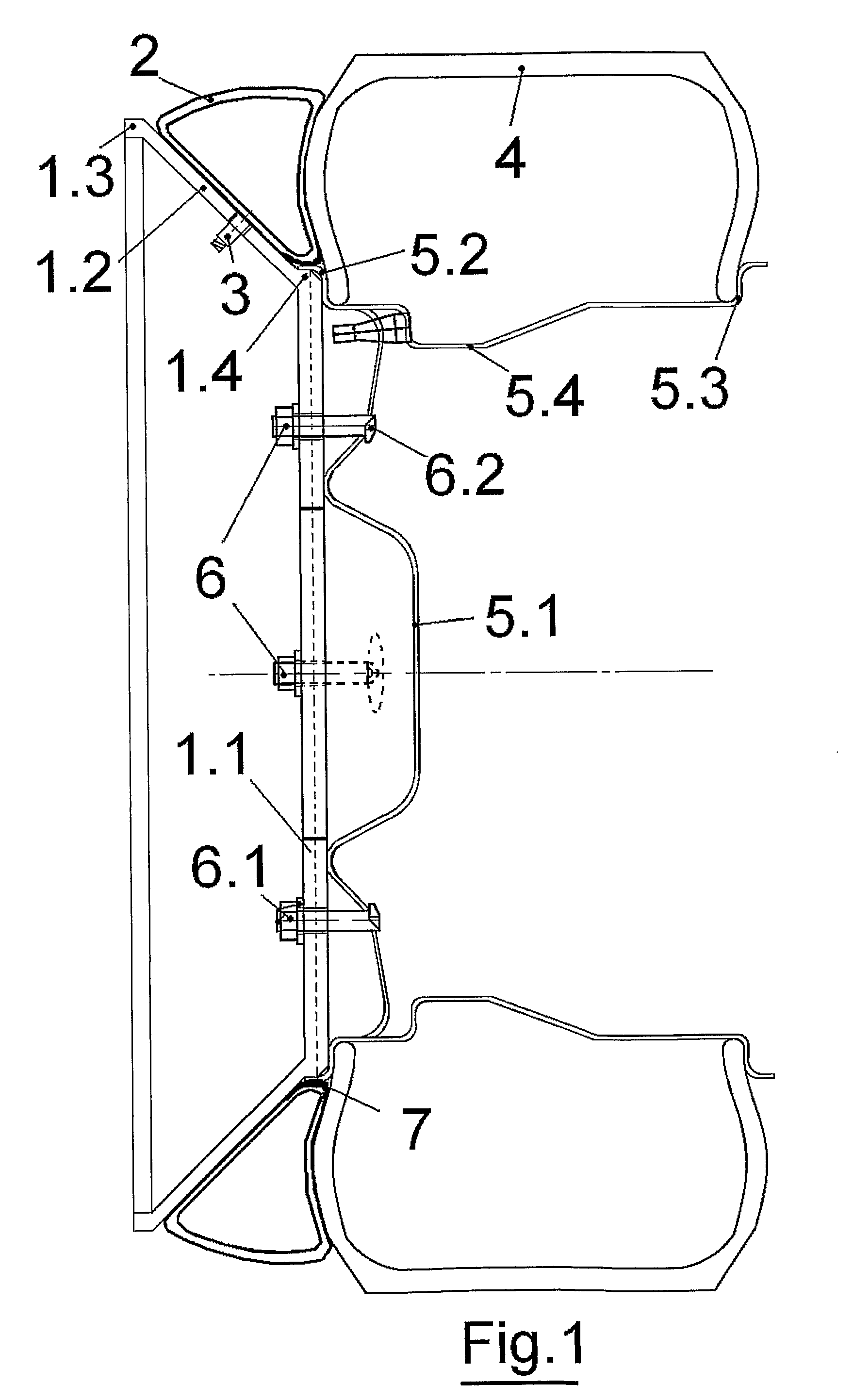
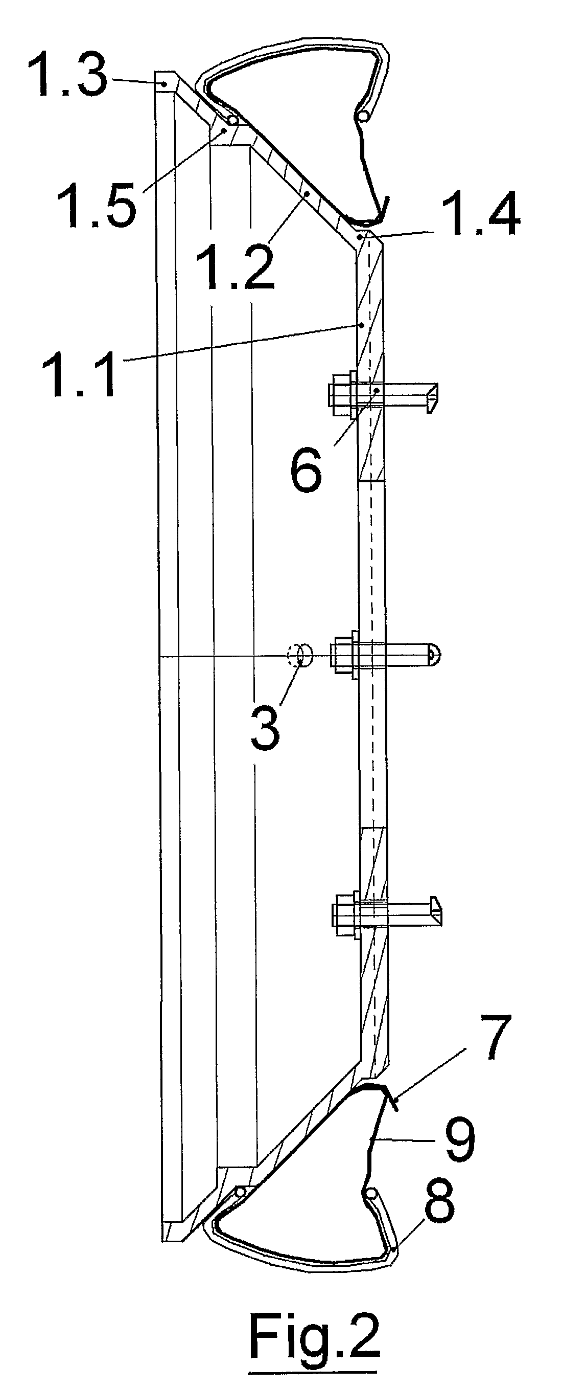
[0006]According to a first characteristic, and for each wheel, it includes a light rim centered and fixed to the outer side of the wheel rim. This light rim comprises a support flange (1.1) that keeps in place the locking bolts and supports the system on the wheel's rim, a rim profile (1.2) that supports the tube and the outer rim reinforcement (1.3). The space between the rim profile (1.2) and the outside bead of the vehicle tire is filled with a thick inflated inner tube (2) that constitutes the additional tread. The outside diameter of this tube is smaller than the outside diameter of the tire that remains the main carrying element. This difference in outside diameter allows easy mounting of the outer anti-sink rim on the wheel as son as there is a risk of sinking the wheel in the sand. It also reduces the risks of contact of the anti-sink rims with the car body at front steered wheels level.
[0007]The structure of the thick inner tube made of a mix of rubber, fibers and fabric bandages gives a good side contact, a good grip and keeps the tread shape for pressures of around one to two bars. The tube is generally mounted when the anti-sink rim is connected to the wheel, however, for the tubes having their fiber reinforcement layers added only on their outside diameter, it is also possible to mount the tube after the anti sink rim is already has been connected.
[0012]In case the car wheel is equipped with a balance weight added on the outer diameter of the rim, it will be necessary to cut and remove from the anti-sink rim both the corresponding part that would otherwise interfere with this weight, and the equivalent mass located diametrically opposite. In that case, the anti-sink rims will be marked so that they will always be mounted on the same matching wheel. The inclined or conical shape of the rim profile induces a straightening of the structure and an easy piling up of the two, four or more rims for a minimum storage volume.
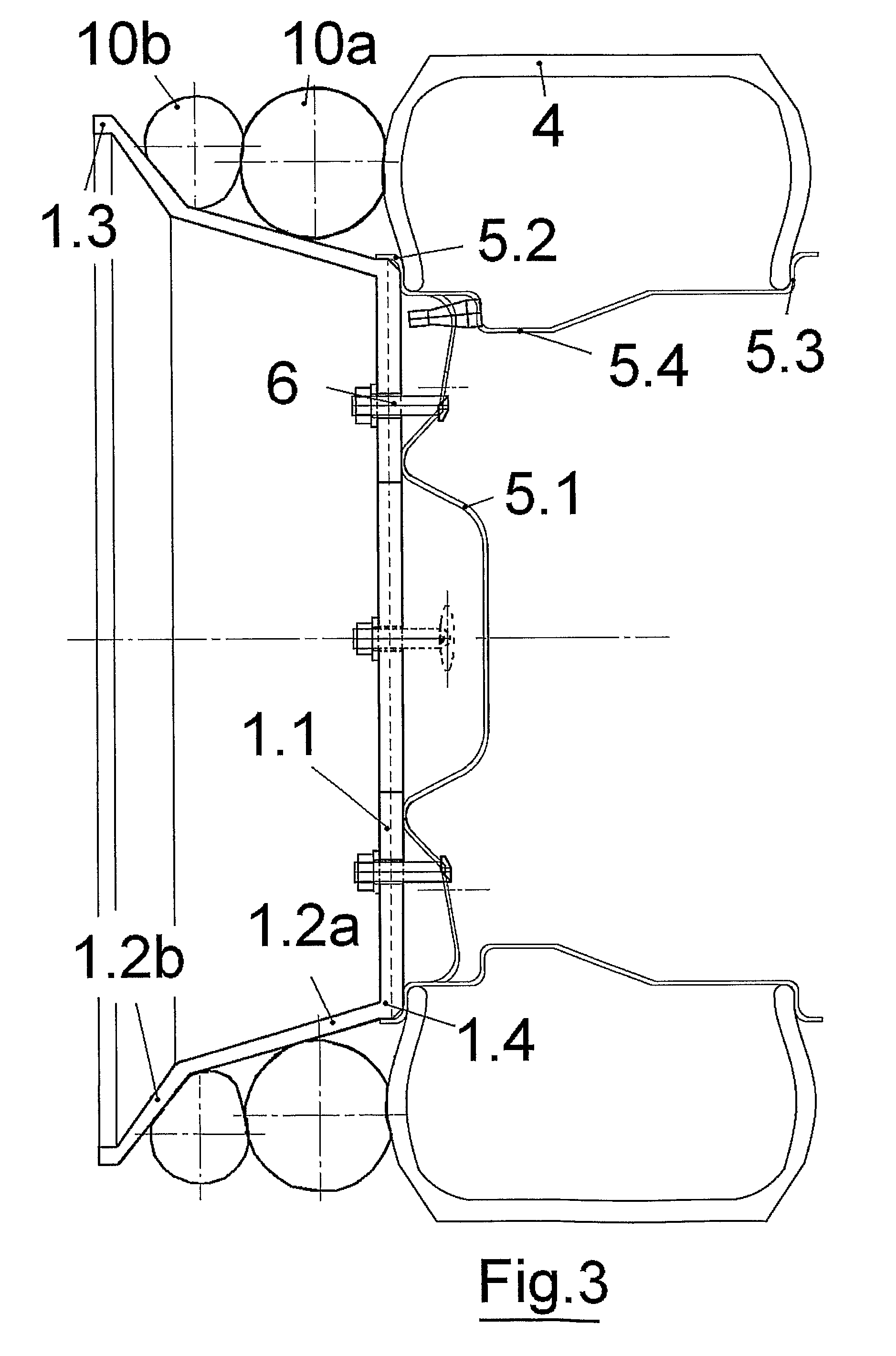
[0014]According to a third characteristic, the anti-sink rim is wider. Its profile (1.2) can be broken down into various segments (1.2a and 1.2b) in order to preserve a good ratio between width, stiffness and the possibility of piling rims in for storage. The tread will be composed of several rings or reinforced chambers (10a and 10b). These kinds of rings ensure enough bearing capacity on many types of ground, like dune sand.
[0018]According to a seventh characteristic, the inner tube and the tire are replaced by a solid rubber bandage with cup shape studs (13) encircling the anti-sink rim. This bandage, once inside, conforms to the shape between the rim profile (1.2) and the wheel tire (4) and presents a succession of cup shaped hollow caps on its tread. This shape resembles a cut up slice of a golf ball. The bandage's hollows reduce the weight, and help, by trapping the sand, contribute to the bearing capacity of the vehicle on sand tracks. The paddle effect of this surface also increases the global wheel grip on the sand.
[0020]According to a ninth characteristic the inner tube and tire are replaced by a solid bandage made of light semi rigid compact material (15), with blades on its outside and encircling the anti-sink rim. This bandage conforms to the shape between the rim profile (1.2) and the wheel tire (4) and provides a tread with blades for paddle effect. This system increases the grip that is already provided by the wheel tire (4) studs.

Problems solved by technology

The main drawback of these remedial solutions is that they do not prevent from another problem further down on the track.
Their effects are very limited in distance.
Further more they require the availability of another vehicle, men or animals for pushing, and there are risks of injuries when pushing or pulling a vehicle, or the tow vehicle can also get stuck.
In addition, special tires are optimized for a specific type of track and may not be best suited for the other sections of the road and it is not conceivable to change tires according to each new type of road encountered.

Method used


Image

  • Anti-sink rim
  • Anti-sink rim
  • Anti-sink rim

Examples


Embodiment Construction

[0073]The realization of different characteristic of the invention is carried out according to the information contained in each of the previous chapters.

[0074]Concerning a regular car, the characteristics of the 1st arrangement are standard. Supposing the car wheel rim has 16 holes, 4 bolts with a single pin (6, 6.1, and 6.2) will be used. The anti-sink rim will be made of a stamped steel sheet 2 mm thick, doubled at the flange (1.1) level by another sheet welded on it. The wheel rim surfaces (5.1 and 5.2) being on the same plane, there is no need of a central part reinforcement (1.6) on the anti-sink rim flange. The outer rim reinforcement (1.3) will consist of a simple fold of the steel sheet at the end of the rim profile (1.2). The protective tape (7) is a 2 mm thick and 20 mm wide rubber stripe with a circumference of 380 mm. The diameter of the anti-sink rim chamber's tread (2) is 550 mm for an inflation pressure of 1.5 bars, and for a 600 mm wheel tire diameter (4). The width...


PUM


Abstract

The invention relates to a device which is used to free a vehicle that has become stuck in terrain or to reduce the risk of same, through the use of an additional tread which is disposed parallel to that of each wheel of the vehicle. The additional tread can take the form of an air chamber (2 or 10a and 10b) which may or may not be covered with a tire (11) or of a band comprising different coupling profiles (13, 14 or 15). Said tread is mounted to an anti-sink rim essentially comprising a conical profile (1.2) and a flange (1.1) which is centered in relation to, and applied against the outer side of the rim of the vehicle wheel using at least three bolts having special heads (6), which are inserted and coupled in respective openings in the flange and rim. The diameter of the system is smaller than that of the wheel in order to facilitate mounting and to reduce the risk of interference with the body of the vehicle. The conical shape of the rim profile (1.2) lends natural stiffness to the system and, when not in use, enables same to be easily stacked in order to minimize the storage space required.

Description

TECHNICAL FIELD[0001]The invention relates to a device that is used to free a road or all tracks vehicle that has become stuck in terrain or to reduce the risk of the same. The terrain is made of sand, mud or snow or other soft material that would lead to the sinking of the wheel in the upper layer of soil together with a reduced traction. According to the terrain characteristics and slope of the track, it also helps reduce the difficulties associated with lack of traction of the vehicle on the track material.BACKGROUND ART[0002]In case a vehicle is stuck, it is known in the vehicle art that one can use special light boards (L×W=2×0.5 m) to function as support and anti skid devices and to be put under the vehicle wheels, use shovels to free the vehicle, or pull the vehicle with a winch and a cable attached to a fix point. To prevent the risk, one can use special tires or snow chains or reduce the tire pressure to increase its contact surface and grip.[0003]Alternatively one can also...

Claims


Application Information

Patent Timeline
IPC IPC(8): B60B15/26
CPCB60B19/04B60B15/263B60B11/10
Inventor BIESSE, PHILIPPE
Owner BIESSE PHILIPPE
Learn More